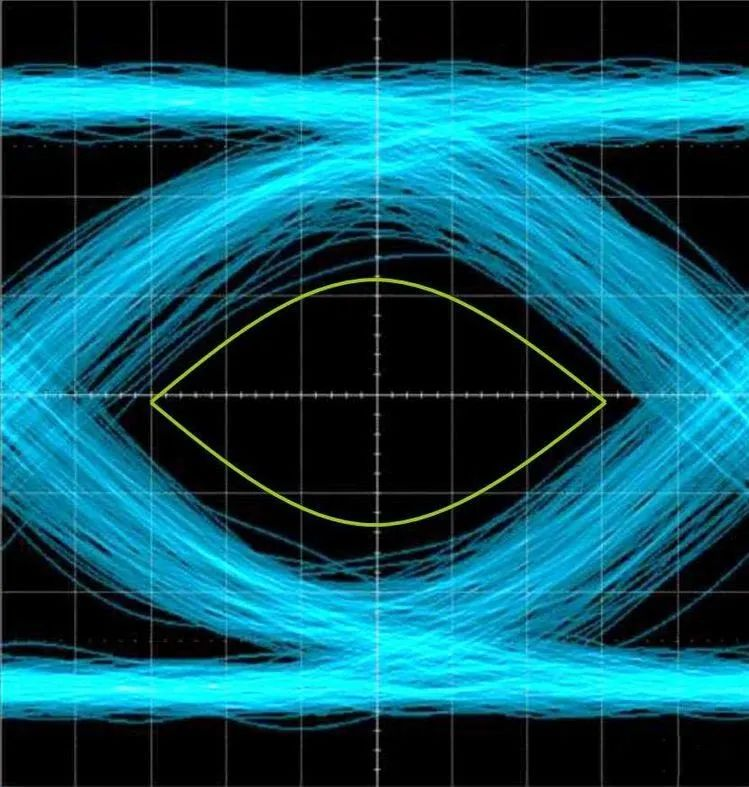
An eye diagram is formed by overlapping each scanned code element waveform due to the afterglow effect of an oscilloscope.
An eye diagram is formed by overlapping each scanned code element waveform due to the afterglow effect of an oscilloscope.
This article will help you understand what an eye diagram on a PCB is, how an eye diagram is formed, what information is contained in an eye diagram, and how to distinguish signal quality based on the eye diagram.
To understand an oscilloscope eye diagram, you need to master the following 4 points:
1. What is an Eye Diagram?
An eye diagram is a graph displayed by accumulating a series of digital signals on an oscilloscope. It contains abundant information. The impacts of inter-symbol interference (ISI) and noise can be observed from the eye diagram, which reflects the overall characteristics of digital signals, thereby evaluating the performance of the system. Therefore, eye diagram analysis is the core of signal integrity analysis for high-speed interconnection systems. In addition, this graph can be used to adjust the characteristics of the receiving filter to reduce inter-symbol interference and improve the transmission performance of the system.
Connect an oscilloscope across the output terminal of the receiving filter, then adjust the scanning period of the oscilloscope to synchronize the horizontal scanning period of the oscilloscope with the period of the received code element. The graph displayed on the oscilloscope screen at this time is called an eye diagram.
The signals measured by an oscilloscope are generally the waveforms of some bits or a certain period of time, which reflect more detailed information, while the eye diagram reflects the overall characteristics of all digital signals transmitted on the link.
The method of observing an eye diagram is: connect an oscilloscope across the output terminal of the receiving filter, then adjust the scanning period of the oscilloscope to synchronize the horizontal scanning period of the oscilloscope with the period of the received code element. The graph displayed on the oscilloscope screen looks like a human eye, so it is called an "eye diagram".
The impacts of inter-symbol interference and noise can be observed from the "eye diagram", thereby evaluating the performance of the system.
In addition, this graph can be used to adjust the characteristics of the receiving filter to reduce inter-symbol interference and improve the transmission performance of the system.
2. How is an Eye Diagram Formed?
For digital signals, the changes between high and low levels can have a variety of sequence combinations.
Taking 3 bits as an example, there are 8 combinations from 000 to 111. Overlapping the waveforms of a sufficient number of the above sequences aligned at a certain reference point in the time domain forms an eye diagram, as shown in the figure below. For test instruments, the clock signal of the signal is first recovered from the signal under test, then the eye diagram is superimposed according to the clock reference, and finally displayed.
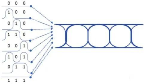
Formation Diagram of Eye Diagram
3. What Information is Contained in an Eye Diagram?
For a real eye diagram, as shown in the figure below, first, we can observe the basic level transition parameters such as the average rise time, fall time, overshoot, undershoot, and threshold level (threshold/crossing percentage) of the digital waveform.
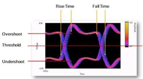
Key Parameter Diagram of Eye Diagram
Rise Time: The rise time of a pulse signal refers to the interval between the two instants when the instantaneous value of the pulse first reaches the specified lower limit and upper limit. Unless otherwise specified, the lower limit and upper limit are set to 10% and 90% of the peak amplitude of the pulse, respectively.
Fall Time: The fall time of a pulse signal refers to the time interval experienced when the pulse drops from 90% to 10% of the peak amplitude.
Overshoot: Also called overshoot, it means the first peak or valley exceeds the set voltage, mainly manifested as a sharp pulse, which can lead to the failure of circuit components.
Undershoot: Refers to the next valley or peak. Excessive overshoot can cause the protection diode to operate, leading to premature failure. Excessive undershoot can cause false clock or data errors.
Threshold Level (Threshold/Crossing Percentage): Refers to the lowest receiving level that the receiver can achieve when the system transmission performance is inferior to a specific bit error rate.
4. How to Distinguish Signal Quality According to the Eye Diagram
The voltage values of high and low levels of the signal cannot be kept completely consistent every time, nor can the rising and falling edges of high and low levels be guaranteed to be at the same time every time. Due to the superposition of multiple signals, the signal lines of the eye diagram become thicker and blurred. Therefore, the eye diagram also reflects the noise and jitter of the signal: on the vertical voltage axis, it is reflected as voltage noise; on the horizontal time axis, it is reflected as time-domain jitter, as shown in the figure below.
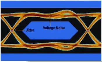
Voltage Noise and Jitter Diagram of Eye Diagram
When noise exists, the noise is superimposed on the signal, and the observed traces of the eye diagram will become blurred. If inter-symbol interference exists at the same time, the "eye" will open smaller. Generally, the larger the eye opens and the higher the eye height of the eye diagram, the better the signal quality.
Eye diagram conditions can be obtained through signal simulation, and then the signal quality can be judged according to the eye diagram. If the eye diagram is poor, the hardware design or PCB design can be adjusted to increase the eye height of the eye diagram and ensure the signal quality of the manufactured products.
About Maxipcb
Maxipcb empowers innovators to turn cutting-edge technologies into reality.
We offer one-stop solutions for design, simulation, testing, PCB manufacturing, component procurement and SMT assembly, enabling efficient development, rapid deployment and risk control across the full product lifecycle.Serving the world in communications, industrial automation, aerospace, automotive, semiconductor and beyond, we build a safer, more connected future together.