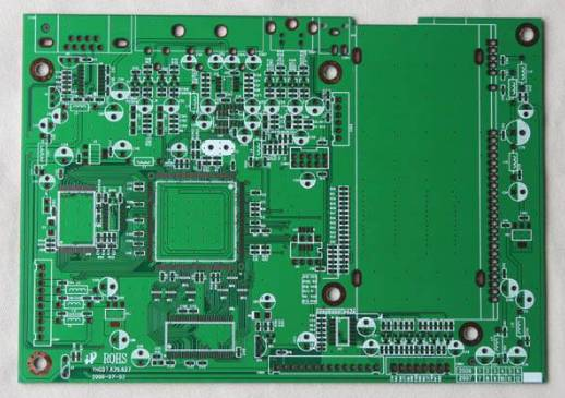
As we all know, manufacturing a PCB board is the process of converting a designed schematic diagram into a physical printed circuit board. Do not underestimate this process; many designs that work in theory are difficult to implement in engineering, or some people can achieve them while others cannot. Therefore, it is not difficult to make a PCB board, but producing an excellent one is no easy task.
As we all know, manufacturing a PCB board is the process of converting a designed schematic diagram into a physical printed circuit board. Do not underestimate this process; many designs that work in theory are difficult to implement in engineering, or some people can achieve them while others cannot. Therefore, it is not difficult to make a PCB board, but producing an excellent one is no easy task.
Two major difficulties in the microelectronics field lie in the processing of high-frequency signals and weak signals. In this regard, the PCB manufacturing level is particularly critical. For the same schematic design and the same components, PCBs produced by different people yield different results. So how can we produce an excellent PCB board?
Based on our past experience, we would like to share our views from the following aspects:
1. Clarify the Design Objectives
When receiving a design task, first clarify its design objectives: whether it is an ordinary PCB board, a high-frequency PCB board, a weak-signal processing PCB board, or a PCB board that handles both high-frequency and weak signals. For an ordinary PCB board, it only needs to have reasonable and neat layout and routing, and accurate mechanical dimensions. If there are medium-load lines and long wires, certain measures must be taken to reduce the load; long wires require enhanced driving, with the focus on preventing long-wire reflection.
When there are signal lines exceeding 40MHz on the board, special considerations must be given to these signal lines, such as crosstalk between lines. At higher frequencies, the length of the routing is subject to stricter restrictions. According to the distributed-parameter network theory, the interaction between high-speed circuits and their connections is decisive and cannot be ignored in system design. As the gate transmission speed increases, the signal opposition on the signal lines increases accordingly, and the crosstalk between adjacent signal lines increases proportionally. Generally, high-speed circuits also have large power consumption and heat dissipation, which should be given sufficient attention when designing high-speed PCBs.
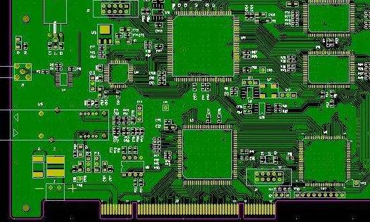
When there are weak signals at the millivolt or even microvolt level on the board, special care must be taken for these signal lines. Because weak signals are too faint, they are highly susceptible to interference from other strong signals, and shielding measures are often necessary; otherwise, the signal-to-noise ratio will be greatly reduced, causing useful signals to be submerged by noise and unable to be effectively extracted. Board testing must also be considered in the design phase; factors such as the physical location of test points and isolation of test points cannot be ignored, as some weak and high-frequency signals cannot be directly measured with probes. In addition, other related factors must be considered, such as the number of board layers, the package shape of the components used, and the mechanical strength of the board. Before making the PCB board, the design objectives must be clear.
2. Understand the Layout and Routing Requirements of Components Based on Their Functions
We know that some special components have special requirements for layout and routing. For example, the analog signal amplifiers used in LOTI and APH require stable power supplies with low ripple. The analog weak-signal section must be kept as far away as possible from power devices. On the OTI board, the weak-signal amplification section is additionally equipped with a shielding cover to block stray electromagnetic interference.
The GLINK chip used on the NTOI board adopts ECL technology, which consumes high power and generates significant heat; special considerations must be made for heat dissipation during layout. If natural heat dissipation is adopted, the GLINK chip must be placed in a well-ventilated area, and the heat dissipated must not significantly affect other chips. If the board is equipped with speakers or other high-power devices, they may cause severe power contamination, which should also be given sufficient attention.
3. Considerations for Component Layout
The first factor to consider in component layout is electrical performance. Components with close wiring relationships should be placed as close together as possible; especially for high-speed lines, the layout should keep them as short as possible. Power signals and weak-signal devices must be separated. On the premise of meeting circuit performance, the layout should also be neat, aesthetic, and easy to test; mechanical dimensions of the board and socket locations must also be carefully considered.
Grounding in high-speed systems and transmission delay on interconnects are also primary considerations in system design. Transmission delay on signal lines greatly impacts overall system speed, especially for high-speed ECL circuits. Although the integrated circuit itself is fast, the delay increase caused by ordinary interconnects on the backplane (approximately 2ns per 30cm line length) can significantly reduce system speed.
Synchronous working components such as shift registers and synchronous counters are best placed on the same plug-in board, because the transmission delay of clock signals to different plug-in boards is unequal, which may cause errors in shift registers. If they cannot be placed on the same board, the length of clock lines from the common clock source to each plug-in board must be equal where synchronization is critical.
Considerations for Routing
With the completion of OTNI and star fiber-optic network designs, more boards with high-speed signal lines above 100MHz will need to be designed. Here we introduce some basic concepts of high-speed lines.
Transmission Line
Any "long" signal path on a printed circuit board can be regarded as a transmission line. If the transmission delay of the line is much shorter than the signal rise time, reflections generated during signal rise will be absorbed, and overshoot, undershoot, and ringing will no longer occur. For most current MOS circuits, the ratio of rise time to line transmission delay is very large, so the routing can be as long as meters without signal distortion. For faster logic circuits, especially ultra-high-speed ECL integrated circuits, the increased edge speed requires greatly reduced routing length to maintain signal integrity without additional measures.
There are two methods to enable high-speed circuits to operate on relatively long lines without severe waveform distortion. TTL uses Schottky diode clamping for fast falling edges, clamping overshoot to a level one diode drop below ground potential, which reduces the subsequent undershoot amplitude. Slow rising edges allow overshoot, but it is attenuated by the relatively high output impedance (50–80Ω) of the circuit in the logic "H" state. In addition, the high noise immunity in the "H" state makes the undershoot problem less prominent. For HCT-series devices, the improvement effect is more significant when Schottky diode clamping is combined with series resistor termination.
When there is fanout along the signal line, the TTL shaping methods described above are insufficient at high bit rates and fast edge speeds, because reflected waves in the line tend to combine at high bit rates, causing severe signal distortion and reduced noise immunity. Therefore, to solve the reflection problem, another method is commonly used in ECL systems: line impedance matching. This method controls reflections and ensures signal integrity.
Strictly speaking, transmission lines are not highly necessary for conventional TTL and CMOS devices with slow edge speeds, nor are they always required for high-speed ECL devices with fast edge speeds. However, when transmission lines are used, they offer the advantages of predictable wiring delay and controllable reflection and oscillation through impedance matching.
-
Five basic factors determine whether to use a transmission line:
(1) Edge rate of the system signal;
(2) Wiring distance;
(3) Capacitive load (amount of fanout);
(4) Resistive load (line termination method);
(5) Allowed percentage of undershoot and overshoot (degree of reduced AC noise immunity).
-
Types of Transmission Lines
(1) Coaxial cables and twisted-pair cables: They are often used for inter-system connections. The characteristic impedance of coaxial cables is usually 50Ω and 75Ω, and twisted-pair cables are usually 110Ω.
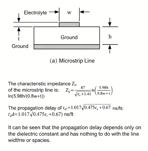
(2) Microstrip line on a printed board
A microstrip line is a strip conductor (signal line) separated from the ground plane by a dielectric. If the thickness and width of the line, as well as the distance to the ground plane, are controllable, its characteristic impedance is also controllable. The characteristic impedance Z₀ of the microstrip line is:
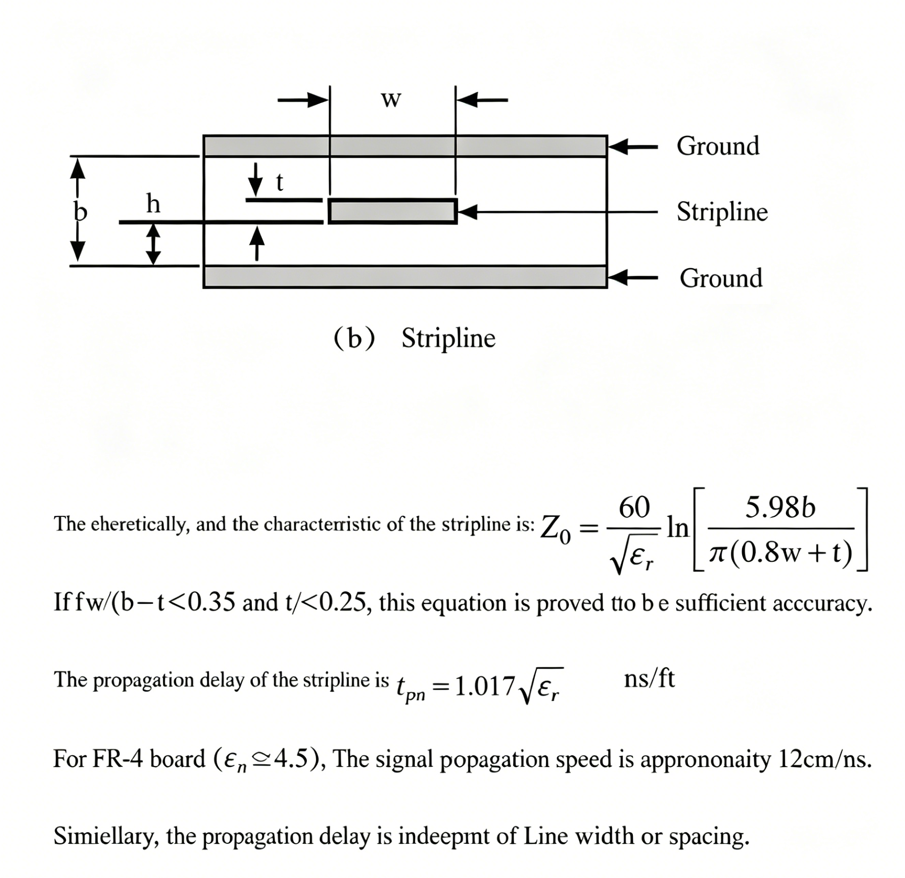
(3) Stripline in a printed board
A stripline is a copper strip placed in the middle of a dielectric between two conductive planes. If the thickness and width of the line, the dielectric constant of the medium, and the distance between the two conductive planes are controllable, the characteristic impedance of the line is also controllable. The characteristic impedance of the stripline is:
-
Terminated Transmission Lines
A transmission line terminated at the receiving end with a resistor equal to the line's characteristic impedance is called a parallel-terminated line. It is mainly used to achieve optimal electrical performance, including driving distributed loads.
Sometimes, to save power consumption, a 104 capacitor is connected in series with the termination resistor to form an AC termination circuit, which effectively reduces DC loss.
A resistor connected in series between the driver and the transmission line, with no termination resistor at the line end, is called series termination. Overshoot and ringing on long lines can be controlled using series damping or series termination technology. Series damping is achieved using a small resistor (typically 10–75Ω) in series with the output of the driving gate. This damping method is suitable for use with lines whose characteristic impedance is controlled (e.g., backplane routing, PCBs without ground planes, and most wrapped wires).
In series termination, the sum of the series resistor value and the output impedance of the circuit (driving gate) equals the characteristic impedance of the transmission line. Series-terminated lines have the disadvantages of only supporting lumped loads at the terminal and long transmission delay. However, this can be overcome by using redundant series-terminated transmission lines.
-
Non-Terminated Transmission Lines
A transmission line can be used without series or parallel termination if the line delay is much shorter than the signal rise time. If the round-trip delay (time for a signal to travel back and forth on the line) of a non-terminated line is shorter than the pulse rise time, the undershoot caused by non-termination is approximately 15% of the logic swing. The maximum open-line length is approximately:
Lmax < tᵣ / (2tₚd)
Where: tᵣ = rise time
tₚd = transmission delay per unit line length
-
Comparison of Several Termination Methods
Parallel-terminated and series-terminated lines each have advantages; the choice depends on the designer's preference and system requirements. The main advantage of parallel-terminated lines is high system speed and complete, undistorted signal transmission on the line. Loads on long lines do not affect the transmission delay or signal edge speed of the driving gate, but increase the signal transmission delay along the long line. When driving large fanouts, loads can be distributed along the line via branch stubs, rather than being lumped at the line end as in series termination.
Series termination allows circuits to drive several parallel load lines. The delay increment caused by capacitive loads on series-terminated lines is approximately twice that of corresponding parallel-terminated lines, and short lines experience slower edge speeds and increased driving-gate delay due to capacitive loads. However, series-terminated lines have less crosstalk than parallel-terminated lines, mainly because the signal amplitude transmitted on series-terminated lines is only half the logic swing, so the switching current is only half that of parallel termination, and lower signal energy results in less crosstalk.
The choice between double-sided and multilayer boards depends on the maximum operating frequency, circuit system complexity, and assembly density requirements. Multilayer boards are preferred when the clock frequency exceeds 200MHz. If the operating frequency exceeds 350MHz, printed circuit boards with polytetrafluoroethylene (PTFE) as the dielectric layer are recommended, due to lower high-frequency attenuation, smaller parasitic capacitance, faster transmission speed, and lower power consumption due to higher Z₀. The following principles apply to PCB routing:
(1) Leave sufficient spacing between all parallel signal lines to reduce crosstalk. If two signal lines are close, a ground line between them can provide shielding.
(2) Avoid sharp bends when designing signal transmission lines to prevent reflection caused by sudden changes in characteristic impedance; uniform arcs of fixed dimensions are preferred.
(3) The width of the printed trace can be calculated using the characteristic impedance formulas for microstrip and striplines above. The characteristic impedance of microstrip lines on PCBs is generally 50–120Ω. To achieve high characteristic impedance, the line width must be very narrow, which is difficult to manufacture.
Considering various factors, a characteristic impedance of approximately 68Ω is generally suitable, as it achieves the best balance between delay and power consumption. A 50Ω transmission line consumes more power; higher impedance reduces power consumption but increases transmission delay.
Negative-line capacitance increases transmission delay and reduces characteristic impedance. However, segments with very low characteristic impedance have large intrinsic capacitance per unit length, so transmission delay and characteristic impedance are less affected by load capacitance. An important feature of properly terminated transmission lines is that branch stubs have little effect on line delay. When Z₀ is 50Ω, the length of branch stubs must be limited to within 2.5cm to avoid severe ringing.
(4) For double-sided boards (or four-layer routing in six-layer boards), traces on both sides of the board should be perpendicular to each other to prevent crosstalk from mutual inductance.
(5) If the PCB is equipped with high-current devices such as relays, indicator lights, and speakers, their ground wires should be routed separately to reduce ground noise. The ground wires of these high-current devices should be connected to an independent ground bus on the plug-in board and backplane, and these independent grounds should also be connected to the system ground point.
(6) If the board has small-signal amplifiers, the weak signal lines before amplification should be kept away from strong signal lines, routed as short as possible, and shielded with ground wires if possible.
About Maxipcb
Maxipcb empowers innovators to turn cutting-edge technologies into reality.
We offer one-stop solutions for design, simulation, testing, PCB manufacturing, component procurement and SMT assembly, enabling efficient development, rapid deployment and risk control across the full product lifecycle.Serving the world in communications, industrial automation, aerospace, automotive, semiconductor and beyond, we build a safer, more connected future together.