For electronic devices, a certain amount of heat is generated during operation, which causes the internal temperature of the device to rise rapidly. If this heat is not dissipated in a timely manner, the device will continue to heat up, components will fail due to overheating, and the reliability of electronic equipment will decrease.
For electronic devices, a certain amount of heat is generated during operation, which causes the internal temperature of the device to rise rapidly. If this heat is not dissipated in a timely manner, the device will continue to heat up, components will fail due to overheating, and the reliability of electronic equipment will decrease.
Therefore, good heat dissipation treatment of circuit boards is very important. Heat dissipation of PCB circuit boards is a crucial link. So what are the heat dissipation techniques for PCB circuit boards? Let's discuss them below.
01 Heat Dissipation Through the PCB Board Itself
The currently widely used PCB substrates are copper-clad/epoxy glass cloth substrates or phenolic resin glass cloth substrates, and a small amount of paper-based copper-clad boards are also used.
Although these substrates have excellent electrical properties and processing performance, their heat dissipation is poor. As a heat dissipation path for high-heat components, it is almost impossible to rely on the PCB itself to conduct heat through the resin; instead, heat is dissipated from the surface of the component to the surrounding air.
However, as electronic products have entered the era of component miniaturization, high-density mounting, and high-heat assembly, it is very insufficient to rely only on the surface of components with very small surface areas for heat dissipation.
At the same time, due to the extensive use of surface mount components such as QFP and BGA, a large amount of heat generated by components is transferred to the PCB board. Therefore, the best way to solve heat dissipation is to improve the heat dissipation capacity of the PCB itself that is in direct contact with the heating components, and conduct or dissipate heat through the PCB board.
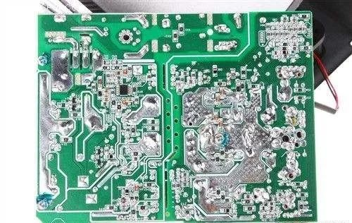
▼ Add heat dissipation copper foil and use large-area power and ground copper foil
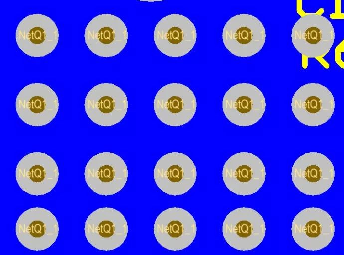
▼ Thermal vias
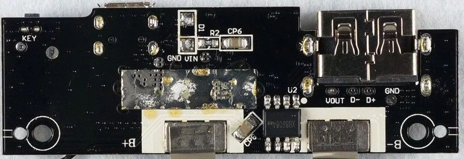
▼ Expose copper on the back of the IC to reduce the thermal resistance between the copper foil and the air
PCB Layout
- Place thermosensitive components in the cold air area.
- Place temperature detection devices in the hottest position.
- Components on the same printed board should be arranged in partitions as much as possible according to their heat generation and heat dissipation capacity. Components with small heat generation or poor heat resistance (such as small-signal transistors, small-scale integrated circuits, electrolytic capacitors, etc.) are placed at the most upstream (inlet) of the cooling air flow, and components with large heat generation or good heat resistance (such as power transistors, large-scale integrated circuits, etc.) are placed at the most downstream of the cooling air flow.
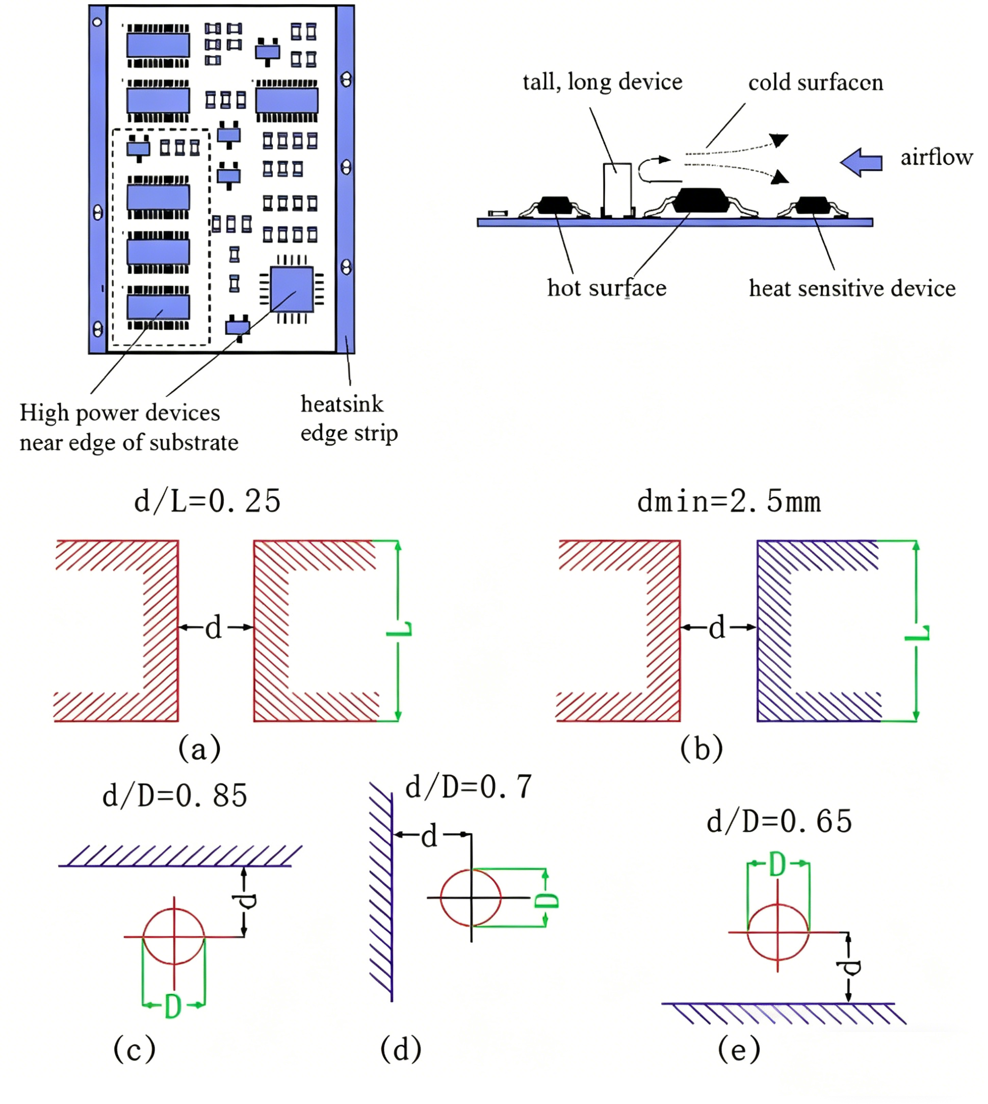
- In the horizontal direction, high-power devices should be arranged as close to the edge of the printed board as possible to shorten the heat transfer path; in the vertical direction, high-power devices should be arranged as close to the top of the printed board as possible to reduce the impact of these devices on the temperature of other components during operation.
- The heat dissipation of printed boards in equipment mainly relies on air flow, so the air flow path should be studied during design, and components or printed circuit boards should be reasonably configured.
- Air always tends to flow where the resistance is small, so when configuring components on a printed circuit board, avoid leaving a large empty area in a certain area. The same problem should also be noted for the configuration of multiple printed boards in the whole machine.
- Temperature-sensitive devices are best placed in the lowest temperature area (such as the bottom of the equipment). Never place them directly above heating devices. Multiple devices are best arranged in a staggered manner on the horizontal plane.
- Arrange the devices with the highest power consumption and the largest heat generation near the best heat dissipation position. Do not place devices with high heat generation at the corners and peripheral edges of the printed board, unless a heat dissipation device is arranged near it.
- When designing power resistors, choose larger devices as much as possible, and adjust the printed board layout to leave enough heat dissipation space for them.
Recommended Component Spacing
02 Add Heat Sinks and Thermal Conductive Plates to High-Heat Devices
When there are a few devices (less than 3) with large heat generation in the PCB, a heat sink or heat pipe can be added to the heating devices. When the temperature still cannot be reduced, a heat sink with a fan can be used to enhance the heat dissipation effect.
When there are many heating devices (more than 3), a large heat shield (plate) can be used. It is a dedicated heat sink customized according to the position and height of the heating devices on the PCB board, or different component height positions are hollowed out on a large flat heat sink. The heat shield is integrally buckled on the component surface to dissipate heat by contacting each component.
However, due to the poor consistency of component heights during assembly and soldering, the heat dissipation effect is not good. Usually, a soft thermal phase change thermal pad is added on the component surface to improve the heat dissipation effect.
03 For Equipment Using Free Convection Air Cooling
It is best to arrange integrated circuits (or other devices) in a longitudinal or transverse manner.
04 Achieve Heat Dissipation Through Reasonable Routing Design
Since the resin in the board has poor thermal conductivity, while copper foil lines and holes are good conductors of heat, increasing the residual rate of copper foil and adding thermal conduction holes are the main means of heat dissipation. To evaluate the heat dissipation capacity of a PCB, it is necessary to calculate the equivalent thermal conductivity (λeq) of the composite material - the insulating substrate for PCB, which is composed of various materials with different thermal conductivities.
05 Component Arrangement by Heat Generation
Components on the same printed board should be arranged in partitions as much as possible according to their heat generation and heat dissipation capacity. Components with small heat generation or poor heat resistance are placed at the most upstream of the cooling air flow, and components with large heat generation or good heat resistance are placed at the most downstream of the cooling air flow.
06 High-Power Device Placement
In the horizontal direction, high-power devices should be arranged as close to the edge of the printed board as possible to shorten the heat transfer path; in the vertical direction, high-power devices should be arranged as close to the top of the printed board as possible to reduce the impact of these devices on the temperature of other components during operation.
07 Air Flow Path Design
The heat dissipation of printed boards in equipment mainly relies on air flow, so the air flow path should be studied during design, and components or printed circuit boards should be reasonably configured. Air always tends to flow where the resistance is small, so when configuring components on a printed circuit board, avoid leaving a large empty area in a certain area. The same problem should also be noted for the configuration of multiple printed boards in the whole machine.
08 Temperature-Sensitive Device Placement
Temperature-sensitive devices are best placed in the lowest temperature area (such as the bottom of the equipment). Never place them directly above heating devices. Multiple devices are best arranged in a staggered manner on the horizontal plane.
09 High-Power Device Placement Near Optimal Heat Dissipation Positions
Arrange the devices with the highest power consumption and the largest heat generation near the best heat dissipation position. Do not place devices with high heat generation at the corners and peripheral edges of the printed board, unless a heat dissipation device is arranged near it. When designing power resistors, choose larger devices as much as possible, and adjust the printed board layout to leave enough heat dissipation space for them.
10 Avoid Hot Spot Concentration
Avoid the concentration of hot spots on the PCB, distribute power as evenly as possible on the PCB board, and maintain uniform and consistent temperature performance on the PCB surface.
It is often difficult to achieve strict uniform distribution in the design process, but it is necessary to avoid areas with too high power density to prevent overheating points from affecting the normal operation of the entire circuit. If conditions permit, it is very necessary to perform thermal efficiency analysis of printed circuits. For example, the thermal efficiency index analysis software modules added in some professional PCB design software can help designers optimize circuit design.
About Maxipcb
Maxipcb empowers innovators to turn cutting-edge technologies into reality.
We offer one-stop solutions for design, simulation, testing, PCB manufacturing, component procurement and SMT assembly, enabling efficient development, rapid deployment and risk control across the full product lifecycle.Serving the world in communications, industrial automation, aerospace, automotive, semiconductor and beyond, we build a safer, more connected future together.