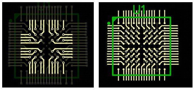
PCB, also known as Printed Circuit Board, realizes the circuit connection and function implementation between electronic components, and is also an important part of power circuit design. This article will introduce the basic rules of PCB layout and routing.
PCB, also known as Printed Circuit Board, realizes the circuit connection and function implementation between electronic components, and is also an important part of power circuit design. This article will introduce the basic rules of PCB layout and routing.
Basic Component Layout Rules
- Layout according to circuit modules. Circuits that implement the same function are called a module. Components in a circuit module should adopt the principle of proximity and concentration, while digital circuits and analog circuits should be separated.
- No components shall be mounted within 1.27mm around non-mounting holes such as positioning holes and standard holes. No components shall be mounted within 3.5mm (for M2.5) and 4mm (for M3) around mounting holes such as screws.
- Avoid routing vias under horizontally mounted resistors, inductors (through-hole), electrolytic capacitors and other components to prevent short circuits between vias and component housings after wave soldering.
- The distance from the outer side of components to the board edge is 5mm.
- The distance between the outer side of surface mount component pads and the outer side of adjacent through-hole components is greater than 2mm.
- Metal housing components and metal parts (shielding boxes, etc.) shall not collide with other components, and shall not be close to printed lines or pads, with a spacing greater than 2mm. The distance from the outer side of positioning holes, fastener mounting holes, elliptical holes and other square holes in the board to the board edge is greater than 3mm.
- Heating elements shall not be close to wires and thermosensitive elements; high-heat devices shall be evenly distributed.
- Power sockets should be arranged around the printed board as much as possible, and the power sockets and their connected bus bar terminals should be arranged on the same side. Special attention should be paid not to arrange power sockets and other soldering connectors between connectors to facilitate the soldering of these sockets and connectors, as well as the design and wiring of power cables. The arrangement spacing of power sockets and soldering connectors should consider the convenience of plugging and unplugging power plugs.
- Layout of other components: All IC components are aligned on one side, the polarity marks of polarized components are clear, and there shall be no more than two polarity marking directions on the same printed board. When two directions appear, the two directions are perpendicular to each other.
- The board surface routing should be properly dense. When the density difference is too large, it should be filled with mesh copper foil, with the grid larger than 8mil (or 0.2mm).
- There shall be no through holes on surface mount pads to avoid solder paste loss causing component cold soldering. Important signal lines shall not pass between socket pins.
- Surface mount components are aligned on one side, with consistent character directions and consistent package directions.
- The polarity marking directions of polarized devices on the same board should be kept consistent as much as possible.
Basic Component Routing Rules
- Routing is prohibited within the area ≤1mm from the PCB board edge and within 1mm around mounting holes.
- Power lines should be as wide as possible, not less than 18mil; signal line width should not be less than 12mil; CPU input and output lines should not be less than 10mil (or 8mil); line spacing should not be less than 10mil.
- Normal vias should not be less than 30mil.
- Dual in-line package: pad 60mil, hole diameter 40mil;
1/4W resistor: 5155mil (0805 surface mount); when through-hole, pad 62mil, hole diameter 42mil;
Non-polar capacitor: 5155mil (0805 surface mount); when through-hole, pad 50mil, hole diameter 28mil.
- Note that power lines and ground lines should be radial as much as possible, and signal lines should not have loop routing.
Improving Anti-interference Ability and Electromagnetic Compatibility
When developing electronic products with processors, how to improve anti-interference ability and electromagnetic compatibility?
1. The following systems require special attention to electromagnetic interference resistance
(1) Systems with particularly high microcontroller clock frequencies and particularly fast bus cycles.
(2) Systems containing high-power, high-current drive circuits, such as spark-generating relays, high-current switches, etc.
(3) Systems containing weak analog signal circuits and high-precision A/D conversion circuits.
2. Measures to increase electromagnetic interference resistance
(1) Select microcontrollers with low frequencies:
Selecting microcontrollers with low external clock frequencies can effectively reduce noise and improve system anti-interference ability. For square waves and sine waves of the same frequency, square waves contain much more high-frequency components than sine waves.
Although the amplitude of the high-frequency components of the square wave is smaller than that of the fundamental wave, the higher the frequency, the easier it is to emit and become a noise source. The influential high-frequency noise generated by microcontrollers is about 3 times the clock frequency.
(2) Reduce distortion during signal transmission:
Microcontrollers are mainly manufactured using high-speed CMOS technology. The static input current at the signal input terminal is about 1mA, the input capacitance is about 10PF, and the input impedance is quite high. The output terminals of high-speed CMOS circuits have considerable load-carrying capacity, that is, a considerable output value. When the output terminal of a gate is led to an input terminal with quite high input impedance through a long line, the reflection problem will be serious, which will cause signal distortion and increase system noise. When Tpd > Tr, it becomes a transmission line problem, and signal reflection, impedance matching and other issues must be considered.
The delay time of a signal on a printed board is related to the characteristic impedance of the lead, that is, to the dielectric constant of the printed circuit board material. It can be roughly considered that the transmission speed of a signal on a printed board lead is about 1/3 to 1/2 of the speed of light. The Tr (standard delay time) of commonly used logic components in systems composed of microcontrollers is between 3 and 18ns.
On a printed circuit board, the delay time on the line is approximately 4~20ns when a signal passes through a 7W resistor and a 25cm long lead. That is to say, the shorter the lead of the signal on the printed circuit board, the better, and the length should not exceed 25cm. Moreover, the number of vias should be as few as possible, no more than 2.
When the rise time of the signal is faster than the signal delay time, it must be processed according to fast electronics. At this time, impedance matching of the transmission line should be considered. For signal transmission between integrated blocks on a printed circuit board, the situation of Td > Trd should be avoided. The larger the printed circuit board, the slower the system speed cannot be.
The following conclusion summarizes a rule for printed circuit board design: The delay time of signal transmission on a printed board should not be greater than the nominal delay time of the device used.
(3) Reduce crosstalk between signal lines:
A step signal with a rise time of Tr at point A is transmitted to terminal B through lead AB. The delay time of the signal on line AB is Td. At point D, due to the forward transmission of the signal at point A, the signal reflection after reaching point B and the delay of line AB, a page pulse signal with a width of Tr will be induced after Td time. At point C, due to the transmission and reflection of the signal on AB, a positive pulse signal with a width twice the delay time of the signal on line AB, that is, 2Td, will be induced. This is crosstalk between signals.
The intensity of the interference signal is related to the di/dt of the signal at point C and the distance between the lines. When the two signal lines are not very long, what is seen on AB is actually the superposition of two pulses.
Microcontrollers manufactured by CMOS technology have high input impedance, high noise, and high noise margin. For digital circuits, superimposing 100~200mv noise does not affect their work. If line AB in the figure is an analog signal, this interference becomes intolerable. If the printed circuit board is a four-layer board with a large area of ground, or a double-sided board with a large area of ground on the reverse side of the signal lines, this crosstalk between signals will be reduced.
The reason is that a large area of ground reduces the characteristic impedance of the signal lines, and the reflection of the signal at terminal D is greatly reduced. The characteristic impedance is inversely proportional to the square of the dielectric constant of the medium between the signal line and the ground, and proportional to the natural logarithm of the medium thickness.
If line AB is an analog signal, to avoid interference from digital circuit signal line CD to AB, there should be a large area of ground under line AB, and the distance between line AB and line CD should be 2~3 times the distance between line AB and the ground. Local shielding ground can be used, with ground wires arranged on the left and right sides of the lead on the side with the lead.
(4) Reduce noise from the power supply:
While providing energy to the system, the power supply also adds its noise to the supplied power. The reset line, interrupt line, and other control lines in the circuit are susceptible to external noise.
Strong interference from the power grid enters the circuit through the power supply. Even in battery-powered systems, the battery itself has high-frequency noise. Analog signals in analog circuits are even less able to withstand interference from the power supply.
(5) Pay attention to the high-frequency characteristics of printed circuit boards and components:
At high frequencies, the distributed inductance and capacitance of leads, vias, resistors, capacitors, and connectors on printed circuit boards cannot be ignored. The distributed inductance of capacitors cannot be ignored, and the distributed capacitance of inductors cannot be ignored.
Resistors produce reflections of high-frequency signals, and the distributed capacitance of leads plays a role. When the length is greater than 1/20 of the wavelength corresponding to the noise frequency, an antenna effect occurs, and noise is emitted outward through the lead.
A via on a printed circuit board causes approximately 0.6pf of capacitance. The packaging material of an integrated circuit itself introduces 2~6pf of capacitance. A connector on a circuit board has a distributed inductance of 520nH. A 24-pin integrated circuit socket for dual in-line packages introduces 4~18nH of distributed inductance.
These small distributed parameters are negligible for microcontroller systems operating at lower frequencies; however, they must be given special attention for high-speed systems.
(6) Reasonable partitioning of component layout:
The position of components on the printed circuit board should fully consider the problem of electromagnetic interference. One of the principles is that the leads between various components should be as short as possible. In terms of layout, the analog signal part, high-speed digital circuit part, and noise source part (such as relays, high-current switches, etc.) should be reasonably separated to minimize signal coupling between them.
Handle the ground wire properly: On printed circuit boards, power lines and ground wires are the most important. The main means to overcome electromagnetic interference is grounding.
For double-sided boards, the layout of ground wires is particularly particular. By adopting the single-point grounding method, power and ground are connected to the printed circuit board from both ends of the power supply, with one power contact and one ground contact. On the printed circuit board, there should be multiple return ground wires, all of which converge to the contact point back to the power supply, which is the so-called single-point grounding.
The so-called separate analog ground, digital ground, and high-power device ground means that the routing is separated, but all converge to this grounding point. When connecting to signals outside the printed circuit board, shielded cables are usually used. For high-frequency and digital signals, both ends of the shielded cable are grounded. For low-frequency analog signals, it is better to ground one end of the shielded cable.
Circuits that are very sensitive to noise and interference or circuits with particularly severe high-frequency noise should be shielded with metal covers.
(7) Make good use of decoupling capacitors:
Good high-frequency decoupling capacitors can remove high-frequency components up to 1GHz. Ceramic chip capacitors or multilayer ceramic capacitors have better high-frequency characteristics. When designing printed circuit boards, add a decoupling capacitor between the power supply and ground of each integrated circuit.
Decoupling capacitors have two functions: on the one hand, they are energy storage capacitors for the integrated circuit, providing and absorbing the charging and discharging energy at the moment the integrated circuit switches on and off; on the other hand, they bypass the high-frequency noise of the device.
A typical 0.1uf decoupling capacitor in digital circuits has a distributed inductance of 5nH, and its parallel resonance frequency is about 7MHz, which means it has a good decoupling effect on noise below 10MHz and almost no effect on noise above 40MHz.
1uf and 10uf capacitors have a parallel resonance frequency above 20MHz, and the effect of removing high-frequency noise is better. It is often advantageous to add a 1uf or 10uf high-frequency decoupling capacitor where the power enters the printed board, even in battery-powered systems.
Add a charge-discharge capacitor, also known as an energy storage capacitor, for every 10 or so integrated circuits, with a capacitance of 10uf. Do not use electrolytic capacitors. Electrolytic capacitors are rolled up with two thin films, and this rolled structure behaves as an inductor at high frequencies. Use tantalum capacitors or polycarbonate capacitors.
The selection of decoupling capacitor values is not strict and can be calculated as C=1/f; that is, 0.1uf for 10MHz, and 0.1~0.01uf for systems composed of microcontrollers.
3. Some experiences in reducing noise and electromagnetic interference
(1) Use low-speed chips instead of high-speed ones if possible, and use high-speed chips only in critical places.
(2) A resistor can be connected in series to reduce the jump rate of the upper and lower edges of the control circuit.
(3) Try to provide some form of damping for relays and other components.
(4) Use a clock frequency that meets system requirements.
(5) The clock generator should be as close as possible to the device using the clock. The quartz crystal oscillator housing should be grounded.
(6) Enclose the clock area with ground wires, and keep the clock lines as short as possible.
(7) I/O drive circuits should be as close as possible to the edge of the printed board to let them leave the printed board as soon as possible. Add filtering to signals entering the printed board, and also add filtering to signals coming from high-noise areas. At the same time, use series terminal resistors to reduce signal reflection.
(8) Unused terminals of MCD should be connected high, grounded, or defined as output terminals. All terminals on integrated circuits that should be connected to power and ground should be connected, not left floating.
(9) Unused gate circuit inputs should not be left floating. The non-inverting input of unused op-amps should be grounded, and the inverting input should be connected to the output.
(10) Printed boards should use 45-degree broken lines instead of 90-degree broken lines for routing to reduce the emission and coupling of high-frequency signals.
(11) Partition the printed board according to frequency and current switching characteristics, and keep noise components further away from non-noise components.
(12) Single-sided and double-sided boards use single-point power supply and single-point grounding. Power lines and ground lines should be as thick as possible. If economically affordable, use multilayer boards to reduce the capacitive inductance of power and ground.
(13) Clock, bus, and chip select signals should be far away from I/O lines and connectors.
(14) Analog voltage input lines and reference voltage terminals should be as far away as possible from digital circuit signal lines, especially clocks.
(15) For A/D devices, it is better to unify the digital part and the analog part rather than cross them.
(16) Clock lines perpendicular to I/O lines cause less interference than parallel I/O lines, and clock component pins are far away from I/O cables.
(17) Component pins should be as short as possible, and decoupling capacitor pins should be as short as possible.
(18) Critical lines should be as thick as possible, with protective grounds added on both sides. High-speed lines should be short and straight.
(19) Noise-sensitive lines should not be parallel to high-current, high-speed switching lines.
(20) Do not route under quartz crystals or under noise-sensitive devices.
(21) Do not form current loops around weak signal circuits and low-frequency circuits.
(22) No signal should form a loop. If unavoidable, make the loop area as small as possible.
(23) One decoupling capacitor per integrated circuit. Add a small high-frequency bypass capacitor next to each electrolytic capacitor.
(24) Use large-capacity tantalum capacitors or polyester capacitors instead of electrolytic capacitors as circuit charge-discharge energy storage capacitors. When using tubular capacitors, the housing should be grounded.
About Maxipcb
Maxipcb empowers innovators to turn cutting-edge technologies into reality.
We offer one-stop solutions for design, simulation, testing, PCB manufacturing, component procurement and SMT assembly, enabling efficient development, rapid deployment and risk control across the full product lifecycle.Serving the world in communications, industrial automation, aerospace, automotive, semiconductor and beyond, we build a safer, more connected future together.