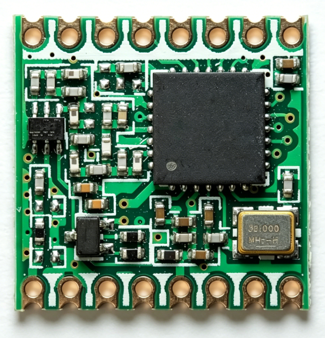
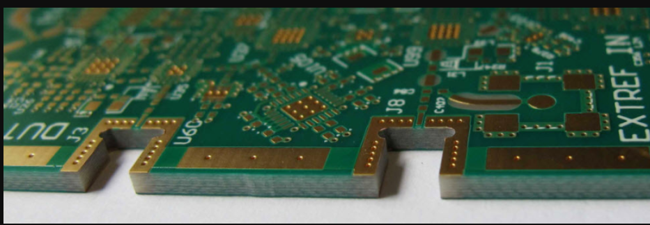
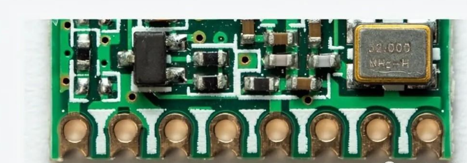
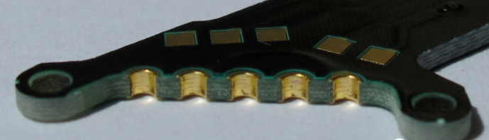
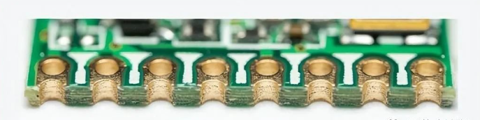
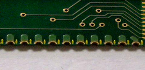
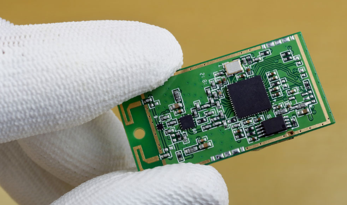
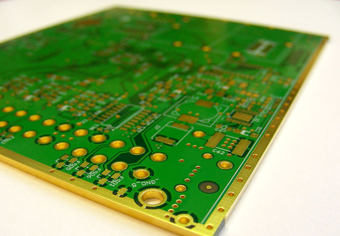
PCB edge plating, also known as edge coating, is a copper plating that extends from the top to the bottom surface of the board and along (at least) one peripheral edge. PCB edge plating provides a robust connection through the PCB and reduces the possibility of equipment failure, especially for small PCBs and motherboards.
Today I will share with you: PCB edge plating, types of PCB edge plating, and how to design PCB edge plating.
I. What is PCB Edge Plating?
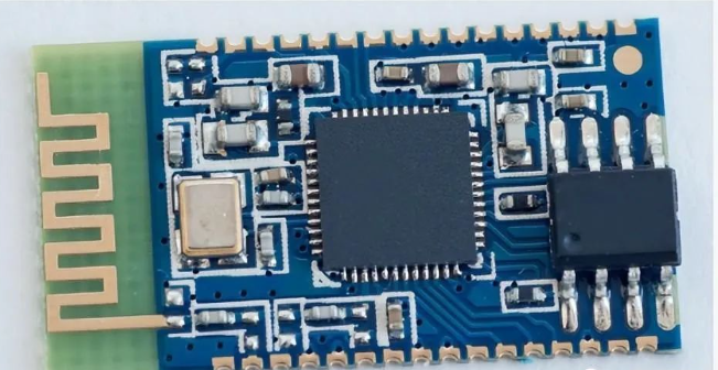
PCB edge plating, also known as edge coating, is a copper plating that extends from the top to the bottom surface of the board and along (at least) one peripheral edge. PCB edge plating provides a robust connection through the PCB and reduces the possibility of equipment failure, especially for small PCBs and motherboards. Examples of this plating are commonly found in Wi-Fi and Bluetooth modules. During the manufacturing process, the edges to be metallized should be milled before the copper plating process. After copper deposition, appropriate surface treatment is applied to the PCB edges.
II. When to Use PCB Edge Plating?
Edge plating is implemented in the following situations:
- Need to improve the conductive capacity of the PCB
- Connections need to be made at the edge of the PCB
- The PCB needs to be protected against lateral impact
- Secondary PCBs are connected to the motherboard via edges
- Need to solder edges to improve assembly
III. Types of PCB Edge Plating
1. Wrap-around Edge Plating
Wrap-around plating routes the metal edge along the side after drilling. The routing process exposes the PCB sidewalls to electroless base copper so that it can be applied simultaneously when applied to drilled holes. In the following case, the base layer creates a conductive surface on which you can electroplate a thicker, more durable copper layer (for better adhesion).
2. Copper Board Edge
To avoid damaging copper, we usually require a minimum distance between copper features and the PCB edge. This distance is:
- 0.25 mm for outer layers, with breakaways
- 0.40 mm for inner layers, with breakaways
- 0.45 mm on all layers, with V-cut scores
The copper-to-board edge distance should only be used for planes and large-area copper regions where any minor damage to the copper will not affect board performance. Traces should not be located within the minimum distance from the board edge to avoid damage. If pads are found within the minimum distance from the board edge, they will be clipped back to restore the minimum copper-free space, unless:
- The pad is part of an edge connector (usually with a beveled edge)
- The pad is marked "up to board edge" on a separate mechanical layer
- Clipping would exceed 25% of the pad surface, which is actually an abnormal situation
3. Edge PTH
Edge PTH are plated holes cut at the edge of the circuit board, also known as butterfly holes, used to connect two PCBs by direct soldering or through connectors. The edge of the PCB must have sufficient free space to secure the circuit board in the production panel during manufacturing. Pads must be present on the top and bottom layers to firmly anchor the plating to the circuit board. For smaller sizes, gold surface finish is preferred.
The following are some points to note:
- The edge of the PCB must have sufficient free space to secure the PCB in the production panel during manufacturing.
- Pads must be placed on the top and bottom layers (and possibly inner layers) to firmly anchor the plating to the PCB.
- As a general rule, holes should be as large as possible to ensure good soldering to the mother PCB, with 0.80 mm and above recommended.
- All surface finishes are acceptable, but I prefer gold over nickel for smaller sizes.
4. Rounded Edge Plating
Rounded edge plating means that most or part of the PCB or cutout is plated from the top surface to the bottom surface. It is mainly used to establish a good ground for metal enclosures or shielding purposes. To produce circuit boards with this type of plating, the board outline is milled before the through-hole plating process. Since the circuit needs to be fixed within the production panel during processing, 100% edge plating is not feasible, and there will be some issues with placing routing tabs. For rounded edge plating, electroless nickel immersion gold (ENIG) is the ideal surface finish.
The following are some points to note:
- A copper strip is required on each side for plating connection.
- 100% plating of the edge is not possible due to the need to fix the circuit in the production panel during processing.
- Clearly indicate in the mechanical layer where rounded edge plating is required.
- Selective electroless nickel immersion gold is the only surface finish suitable for rounded edge plating.
IV. How to Design PCB Edge Plating?
1. PCB Edge Plating Guidelines
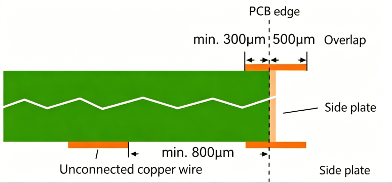
Define the copper plating area using overlapping copper in the design/layout file. This additional copper deposition can be copper pads, surfaces, or traces. To ensure the manufacturability of side plates, the metallized area must be defined using overlapping copper (copper surfaces, pads, or tracks) in the CAD layout.
- Minimum overlap: 500 μm.
- On the connection layer, a minimum of 300 μm connecting copper wire must be defined.
- On non-connection layers, copper should have a minimum gap of 800 μm from the outer contour.
2. Metallization Plating Process
In this process, only four steps need to be performed in the following order: Drilling → Milling metal slots → Decontamination → Electroless copper plating. The external contours that need to be metallized must be milled before the through-hole plating process, as edge metallization is performed during this manufacturing step. After copper deposition, the intended surface finish is finally applied to the edges.
3. Manufacturing Issues
- Copper Peeling - Plating on large substrate surfaces may cause copper peeling due to lack of adhesion. This problem is first solved by roughening the surface through a combination of chemical and other proprietary methods. Next, direct metallization with higher copper bonding strength is used to prepare the plating surface.
- Burrs - Edge plating may produce burrs during the final processing in some plating processes. A modified proprietary process flow is required so that burrs are polished to the edges of the features.
4. Fab House Notes
- Excessively large gold pad antenna positions affect soldering or signal transmission.
- Inner edge pads connected to wires on the board may cause short circuits.
- Stamp holes designed at the edge grinding slot must be processed in the second drilling operation.
- Continuous metallization of the outer edge is not possible by manufacturing individual PCBs as panels for process-related reasons. Metallization cannot be applied at the locations of the small panel bridges. The sliding plating metallization layer can be covered with solder mask.
- When purchasing edge-sealed boards, you must confirm with the PCB supplier the possibility of manufacturing the PCB using the plating process and the extent to which the manufacturer can edge-seal the PCB. Gerber files or factory drawings should indicate on the mechanical layer where they need sliding plating and the surface finish they require.
V. Benefits of PCB Edge Plating
- Enhanced Current Conduction - Improved current-carrying capacity increases the reliability and quality of the circuit board. In addition, the correct level of conduction is ideal for components to operate as required, and it also protects vulnerable edge connections.
- Signal Integrity - Edge plating enhances signal integrity by preventing interference from entering internal electrical pulse transmission.
- Heat Distribution - Since plated edges are metallic, they create additional cooling surface area for dissipating heat into the surrounding air. Metal surfaces improve the reliability of the circuit board, especially when components are heat-sensitive.
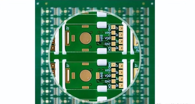
- Better EMC/EMI Performance - Metallized edges allow stray currents to escape, preventing the generation of sporadic electric and magnetic fields.
- Improved Electromagnetic Compatibility - Edge plating enhances the electromagnetic compatibility of multilayer boards.
- Protection Against Electrostatic Damage - When handling circuit boards, static electricity can strike sensitive components, and metal surfaces help absorb static electricity.
VI. Applications of PCB Edge Plating
- Improve EMC performance by shielding internal areas of multilayer boards (e.g., high-frequency circuit boards)
- Cooling function where edges serve as additional cooling surfaces, allowing active heat dissipation
- Enclosure connections
- Board-to-board connections (see plated half-holes)
The above is the knowledge about PCB edge copper plating.
About Maxipcb
Maxipcb empowers innovators to turn cutting-edge technologies into reality.
We offer one-stop solutions for design, simulation, testing, PCB manufacturing, component procurement and SMT assembly, enabling efficient development, rapid deployment and risk control across the full product lifecycle.Serving the world in communications, industrial automation, aerospace, automotive, semiconductor and beyond, we build a safer, more connected future together.