Differential pairs in high‑speed serial links require tight control of impedance, skew, and coupling to limit reflections, mode conversion, and crosstalk. At multi‑gigabit data rates, small deviations in trace geometry, routing symmetry, or material properties can degrade the eye diagram and lead to protocol non‑compliance.
Differential pairs in high‑speed serial links require tight control of impedance, skew, and coupling to limit reflections, mode conversion, and crosstalk. At multi‑gigabit data rates, small deviations in trace geometry, routing symmetry, or material properties can degrade the eye diagram and lead to protocol non‑compliance.
This article reviews the primary signal integrity requirements for differential pairs in high‑speed serial interfaces: differential impedance control, skew management, crosstalk reduction, and PCB layout techniques that preserve signal quality from the driver to the receiver.
Differential Impedance Control
Differential impedance is the primary electrical parameter that governs signal transmission on routed differential pairs. It equals twice the odd‑mode impedance of each line and depends on width, intra‑pair spacing, copper thickness, dielectric height, and dielectric constant. Common targets for serial interfaces are 85–100 Ω: PCIe Gen 4 and Gen 5 specify 85 Ω, USB 3.2 and USB4 target 90 Ω, and LVDS typically specifies 100 Ω.
As shown in Figure 1, the differential impedance in both microstrip and stripline configurations depends on trace width, spacing, and dielectric geometry.
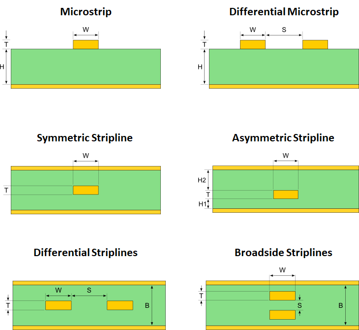
Figure 1. Differential impedance is determined by trace width, spacing, and dielectric geometry in microstrip and stripline structures.
Maintaining the target impedance requires a controlled stack‑up. Trace geometries must be correlated with field solvers or the manufacturer’s impedance table, and the width and spacing should be kept constant over the entire length of the pair.
Discontinuities such as neck‑downs, anti‑pads, asymmetric via structures, and unbalanced component pads introduce local impedance perturbations, which cause reflections and reduce eye opening. Small passive packages – typically 0402 or smaller for AC coupling capacitors – and symmetrical placement of the two legs minimise component‑induced asymmetry.
A solid and continuous reference plane beneath or around the pair is equally critical. Microstrip pairs are routed over a continuous ground plane, while stripline pairs are routed between ground or power planes. Splits, voids, or gaps beneath the pair raise the local impedance and increase radiated fields. Impedance tolerance requirements, typically ±10 %, should appear in fabrication notes and be enforced in the PCB tool as net‑specific constraints.
Closed‑form equations such as those in IPC‑2141 provide approximations at lower frequencies, but their accuracy degrades for many geometries at high frequencies. Field‑solver‑based tools, including calculators such as Polar SI9000, give more reliable starting geometries. For critical links, S‑parameter or TDR simulation verifies the realised impedance before fabrication.
Skew Management
Skew is the difference in propagation delay between the P and N legs of a differential pair. It converts differential energy into common‑mode noise, reduces eye opening, and increases electromagnetic radiation. At multi‑gigabit data rates, the intra‑pair skew budget is very tight. PCIe Gen 5 allows only tens of picoseconds, which corresponds to a few mils of length matching on standard FR‑4.
One of the most common causes of skew is asymmetric routing. As shown in Figure 2, skew caused by unequal path lengths between the legs of a differential pair is corrected by distributing serpentine tuning, while avoiding local discontinuities.
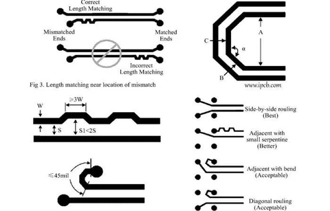
Figure 2. Differential‑pair skew is corrected by length matching; distributed serpentine routing is preferred over localised tuning to minimise discontinuities.
Keeping the two legs geometrically symmetrical – with the same number of bends, matching via structures, and parallel routing on the same reference plane – eliminates most routing‑induced delay mismatches.
When length tuning is required, serpentine sections on the shorter leg restore edge alignment. Distributed tuning over a longer routed segment is better than compact serpentines placed near the connector or receiver, which introduce local capacitive loading and crosstalk.
Other contributors include via structures and material effects. Each via adds capacitive loading and, if not back‑drilled, leaves a stub that resonates at a frequency inversely proportional to stub length. Matching via placement on both legs, combined with back‑drilling in high‑speed designs, keeps via‑induced skew within budget.
Material properties introduce a less obvious but important skew mechanism. Glass‑weave variation in standard FR‑4 laminates can add 10–100 ps of skew at speeds of 10 Gbps and above, even when trace lengths are matched. One leg may pass mainly over glass bundles while the other passes over resin pockets, producing different effective dielectric constants and propagation velocities.
Low‑Dk, low‑variation laminates, slight trace angle offsets relative to the weave direction, or materials that account for weave‑induced skew can reduce this effect in demanding designs. Skew budgeting should consider the entire signal path, including package traces, connector pins, and via delays, not just the PCB trace length.
Crosstalk Reduction
Differential signalling rejects common‑mode noise and provides good immunity to external aggressors. When spacing and referencing are insufficient, parallel high‑speed net pairs can still couple to each other or to adjacent single‑ended nets.
As illustrated in Figure 3, crosstalk arises from electromagnetic coupling between adjacent conductors and increases as spacing decreases and parallel routing length increases.
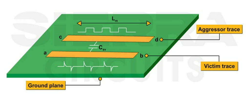
Figure 3. Crosstalk occurs when an aggressor trace couples energy into a nearby victim trace; coupling increases with reduced spacing and longer parallel routing lengths.
Tight intra‑pair coupling – the small gap between the P and N legs – reduces loop area and radiated fields, thereby improving common‑mode rejection. Inter‑pair spacing controls crosstalk between adjacent differential pairs.
A common guideline is that the edge‑to‑edge spacing should be at least three times the trace width, or roughly five times the intra‑pair spacing. This keeps differential crosstalk within acceptable limits for most multi‑gigabit interfaces. A closer reference plane reduces the inter‑pair spacing required for a given crosstalk target, which is one reason why stripline routing offers better crosstalk performance than microstrip at the same pitch.
Physical separation between aggressor nets and sensitive differential channels is also critical. Clock traces, DDR buses, and fast‑switching power nets should not run parallel to PCIe, USB, or LVDS pairs over long distances. Long parallel runs couple energy in proportion to the coupling length, regardless of spacing. Routing strategies that minimise parallel overlap, combined with layer assignments that place sensitive pairs away from noisy nets, are more effective than simply adjusting spacing.
PCB Layout Techniques for High‑Speed Serial Interfaces
High‑speed serial interfaces such as PCIe Gen 4/5, USB4, and LVDS require consistent, symmetric, and discontinuity‑minimised routing. Effective layout begins at the routing channel level. Each pair should be as straight as possible with minimal layer changes. When layer transitions are necessary, both legs should transition together through matched via structures.
Maintaining constant pair spacing and width, including through bends, preserves differential impedance. Shallow 45‑degree bends or arc‑based routing reduce impedance perturbations compared with 90‑degree turns. AC coupling capacitors, ESD protection devices, and connector pads should be placed symmetrically on both legs, with stub lengths kept as short as possible.
As shown in Figure 4, asymmetric component placement leads to imbalance between the legs of a differential pair, while symmetric placement preserves signal integrity.
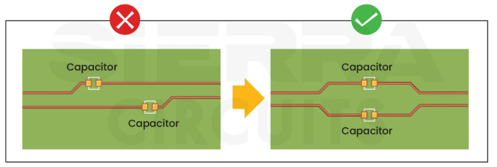
Figure 4. Symmetrical component placement maintains differential‑pair balance, whereas asymmetrical placement introduces discontinuities and degrades signal integrity.
Component‑induced asymmetry is a common source of mode conversion that impedance control alone cannot correct.
Constraint‑driven routing enforces these requirements. PCB design tools allow net‑specific rules for differential impedance, intra‑pair spacing, length, skew tolerance, and via usage. Defining these constraints before routing begins prevents manual edits or auto‑router decisions from breaking pair symmetry. For PCIe Gen 5 and USB4 designs, which run at 32 GT/s and 40 Gbps, SI simulation using extracted S‑parameters and eye‑diagram analysis should validate the channel before fabrication.
Mechanical design also affects signal integrity. Mounting hardware such as brackets and jack screws near connectors rather than at board corners reduces PCB flexing and solder‑joint stress during assembly and thermal cycling.
Connectors placed close to rigid mounting points on the board experience less thermal‑induced displacement, which is particularly important in differential connector systems where contact geometry affects impedance and insertion loss.
Summary
Signal integrity in differential‑pair design for high‑speed serial links depends on the coordinated control of impedance, timing, coupling, and layout geometry. Differential impedance is determined by stack‑up and trace geometry and must be maintained constant along the routed length, with field‑solver verification for demanding interfaces such as PCIe Gen 5 and USB4.
Skew management requires symmetric routing, distributed length tuning, matched via structures, and attention to glass‑weave effects at higher data rates. Crosstalk control relies on tight intra‑pair coupling, adequate inter‑pair spacing, and separation from aggressive nets.
These requirements extend to layout practices including symmetric component placement, minimised discontinuities, constraint‑driven routing, and SI simulation that ensures consistent signal integrity from driver to receiver.
