If you think the rigid PCB manufacturing process is complex, then flexible PCB manufacturing seems to be at another level of complexity.
If you think the rigid PCB manufacturing process is complex, then flexible PCB manufacturing seems to be at another level of complexity. However, many of the same steps used in standard rigid circuit board manufacturing are conceptually similar to flexible PCB manufacturing. This guide outlines all the steps implemented in the flexible PCB manufacturing process. These processes are very similar to rigid PCB manufacturing but involve a different set of materials.
Flexible Stack-up
At first glance, a typical flexible circuit board or rigid-flex circuit board looks simple. However, its nature requires several additional steps to be performed during the construction process. The starting point for any rigid-flex circuit board is always a single-sided or double-sided flexible layer. Manufacturers can start with pre-laminated flex with foil, or they can start with unclad PI film and then laminate or plate copper for the initial cladding. Laminated films require a thin layer of adhesive, while adhesive-free cladding requires a "seed" copper layer. This seed layer is initially implanted using vapor deposition techniques (i.e., sputtering) and provides the key for electroless copper plating. The drilling, plating, and etching steps for this single-sided or double-sided flexible circuit are roughly the same as those for a typical double-sided inner core in rigid circuit boards.
Flexible Manufacturing Steps
The following steps show the creation of a typical double-sided flexible circuit.
Step 1: Apply Adhesive/Seed Coating
Apply epoxy or acrylic adhesive, or use sputtering to create a thin copper layer for plating adhesion.
Step 2: Add Copper Foil
Add copper foil by lamination to the adhesive (the more mainstream method) or electroless plating to the seed layer. New manufacturing processes from material suppliers allow adhesive-free lamination using rolled annealed copper as an alternative.
Step 3: Drilling
Holes for vias and pads are typically mechanically drilled. Multiple plated flexible substrates can be drilled simultaneously by combining them from multiple reels on a roll, drilling between work boards, and then rolling out to separate reels on the other side of the drilling machine. Pre-cut flexible panels can be bonded and drilled between rigid blanks in a manner also similar to how rigid inner cores are drilled, but it requires more careful registration and alignment accuracy will be reduced. For ultra-small holes, laser drilling can be used, but the cost increases significantly because each film layer must be drilled individually. Excimer (ultraviolet) or YAG (infrared) laser machines are used for higher precision (microvias), and CO2 lasers for medium holes (4+ mils). Large holes and cutouts require punching, which is a separate processing step.
Step 4: Through-Hole Plating
After drilling the holes, copper is deposited and electroless plated in the same manner as for rigid PCB inner cores (commonly referred to as Cuposit). It is recommended that the through-hole plating thickness in flexible circuits be at least 1 mil to increase mechanical support for pads or vias, whereas a typical low-cost rigid PCB may only have ½ mil plating thickness.
Step 5: Etch Resist Printing
Apply a photosensitive resist to the film surface and, using the desired mask pattern, expose and develop the resist prior to chemical etching of the copper.
Step 6: Etching and Stripping
After etching the exposed copper, the etch resist is chemically stripped from the flexible circuit.
Step 7: Coverlay
The top and bottom areas of the flexible circuit are protected by a coverlay, which is cut to shape. There may be portions of the flexible circuit where components are actually mounted, in which case the coverlay also acts as a solder mask. The most common coverlay material is an additional polyimide film with adhesive, but adhesive-free processes can also be used. In the adhesive-free process, a photoimageable solder mask (the same as used for rigid board sections) is used, essentially printing the coverlay onto the flexible circuit. For rougher, cheaper designs, screen printing is also an option, with the cover coating finally cured by ultraviolet irradiation. Essentially, the difference is that a coverlay is a laminated film, while a cover coat is an applied material coating that then requires curing.
Step 8: Singulating the Flexible Boards
The final step in creating a flexible circuit is to cut it out. This is commonly referred to as "blanking". The cost-effective blanking method for high volumes is via hydraulic press and die sets, which involves considerable tooling costs. However, this method can blank out many flexible circuits simultaneously. For prototypes and small runs, a blanking knife is used. A blanking knife is simply a long blade bent into the shape of the flexible circuit outline and secured in a routing groove on a backboard (MDF, plywood, or thick plastic such as Teflon). The flexible circuit is then pressed into the blanking knife to make the cut.
Lamination and Routing
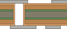
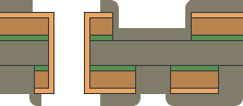
If the flexible circuit is to form part of a rigid/flex combined stack-up (which is what we are interested in), the process does not stop here. We now have a flexible circuit that needs to be laminated between rigid sections. This is the same as for separate drilled, plated, and etched inner core layers, except that it is thinner and more flexible due to the absence of glass fiber. However, as mentioned earlier, less flexible layers made from PI and glass can be used depending on the target application. Because it is laminated between rigid sections, it must ultimately be fitted into a panel that also matches the rigid circuit board panel sections. Flexible circuits that are not bonded to rigid sections are temporarily glued to a rigid backboard of MDF or FR-4 type material.
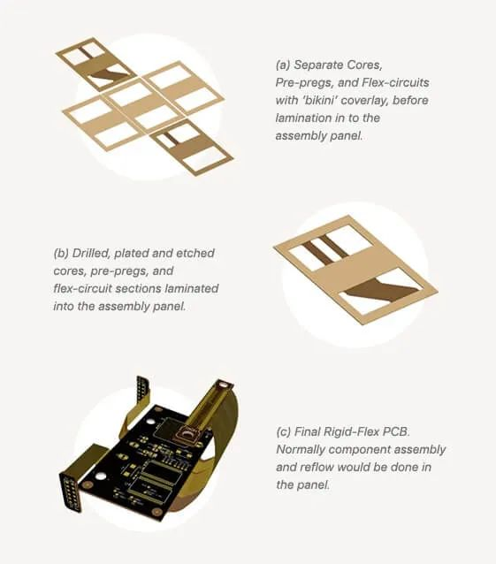
How etched, plated, coverlayed, and blank flexible panels are bonded to glass epoxy rigid panels
Flexible circuits are laminated into the panel together with rigid sections and any other flexible sections, with additional adhesive, heat, and pressure. Unless you are designing multilayer flex, multiple flexible sections are not laminated adjacent to each other. This usually means a maximum of 2 copper layers per flexible section so that flexibility can be maintained. These flexible sections are separated by rigid pre-pregs and inner cores, or by PI bonding sheets using epoxy or acrylic adhesives.
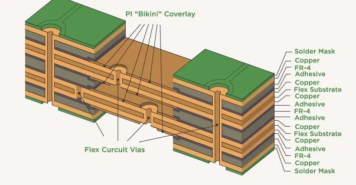
Essentially, each rigid panel is individually routed in the areas that allow the flexible panel to bend. This is an example process for laminating into a rigid-flex circuit board with two 2-layer flexible circuits embedded between three rigid sections. The layer stack-up looks as follows.
Note: Many designers shy away from using adhesives due to unacceptable z-axis expansion during reflow soldering.
In the example stack-up shown above, there are two pre-etched and cut flexible circuits, each double-sided and plated. The flexible circuits have been blanked into final assembly panels including frame borders — this will keep the flexible circuits flat during final assembly after lamination with the rigid panel sections. There are certainly some potential hazards with insufficient support for flexible circuit bends and large opening sections during assembly, especially at the high temperatures of a reflow oven.
While this example does show adhesive layers, it is important to note that many designers shy away from adhesives due to unacceptable z-axis expansion during reflow. However, FR-4 pre-preg and thermoset epoxy effectively achieve the desired result and are the de facto "bonding" layers. Additional adhesion is achieved by treating the copper on the flexible layers to improve "tooth" into the laminating pre-preg. Shown here are adhesive-free double-sided flexible laminates. These are entirely polyimide films with bondable polyimide coatings bonded to copper foil. DuPont Pyralux and Rogers Corp. R/Flex are popular adhesive-free laminate materials.
A coverlay is also applied — either like a sticker laminated with adhesive, or via the photo-printing process mentioned earlier. Once the final flexible and rigid panels in this 6-layer stack-up are placed together, they are laminated with the final copper foil layers on the outermost (top and bottom) sides. Then, another drilling for through-hole plating from top to bottom is completed. Laser-drilled blind vias (top to first flex, bottom to last flex) can also be used, which again increases the design cost. The holes are plated from top to bottom, and blind vias if selected, and the outer layer copper patterns are finally etched. The final steps are printing of the top and bottom solder masks, top and bottom silkscreens, and corrosion-resistant plating (e.g., ENIG) or Hot Air Solder Leveling (HASL).
When you are ready to create documentation for the rigid-flex PCB manufacturing process and plan new designs for manufacturing, use the full set of CAD capabilities and automated drafting tools in the Draftsman package within Altium Designer. When you are ready to release your design data to manufacturers, you can easily share and collaborate on your designs through the Altium 365 platform. You can find everything you need to design and produce advanced electronic products in one software package.
About Maxipcb
Maxipcb empowers innovators to turn cutting-edge technologies into reality.
We offer one-stop solutions for design, simulation, testing, PCB manufacturing, component procurement and SMT assembly, enabling efficient development, rapid deployment and risk control across the full product lifecycle.Serving the world in communications, industrial automation, aerospace, automotive, semiconductor and beyond, we build a safer, more connected future together.