
The precautions for on-board clocks mainly include the following aspects:
-
Layout
a. The clock crystal and related circuits should be placed in the central position of the PCB and should have a good ground plane, rather than being close to the I/O interface. The clock generation circuit must not be made in the form of a daughter card or daughter board; it must be implemented on a separate clock board or carrier board.
As shown in the figure below, for the part in the green box, it is best not to route traces on the layer below.
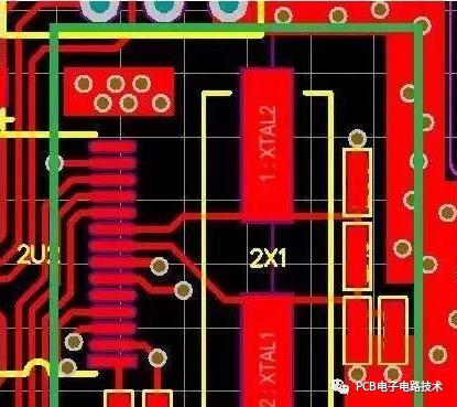
b. In the PCB clock circuit area, place only devices related to the clock circuit and avoid placing other circuits. Do not route other signal lines near or under the crystal: use a ground plane under the clock generation circuit and crystal. If other signals pass through this plane, it violates the image-plane function. If signals are allowed to cross this ground plane, very small ground loops will exist and affect the continuity of the ground plane, and these ground loops will cause problems at high frequencies.
c. For the clock crystal and clock circuit, shielding measures can be used for shielding.
d. If the clock housing is metal, copper must be poured under the crystal during PCB design, and this part must be well electrically connected to the complete ground plane (grounded through multiple vias).
Benefits of grounding under the clock crystal:
The circuit inside the crystal oscillator generates RF current. If the crystal is packaged in a metal housing, the DC power pin is the reference for the DC voltage and for the internal RF current return path of the crystal, and transient currents generated by RF radiation on the housing are released through the ground plane. In short, the metal housing is a single-ended antenna; the nearby image layer and ground plane layer—sometimes two or more layers—are sufficient for radiative coupling of RF current to ground. Grounding under the crystal is also beneficial for heat dissipation.
Grounding under the clock circuit and crystal will provide an image plane, which can reduce common-mode currents generated in the associated crystal and clock circuit, thereby reducing RF radiation. The ground plane also absorbs differential-mode RF current. This plane must be connected to the complete ground plane at multiple points and require multiple vias, which can provide low impedance. To enhance the effect of this ground plane, the clock generation circuit should be close to this ground plane.
SMT-packaged crystals will radiate more RF energy than metal-housing crystals: because surface-mount crystals are mostly plastic-packaged, the RF current inside the crystal will radiate into space and couple to other devices.
-
Shared clock routing
For fast-edge signals and clock signals, a radial topology connection is better than daisy-chaining networks from a single common driver source. Each trace should be routed with termination measures according to its characteristic impedance.
-
Clock transmission line requirements and PCB layer stackup
Clock routing principles: arrange a complete image plane layer adjacent to the clock routing layer, reduce trace length, and perform impedance control.
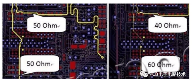
Incorrect cross-layer routing and impedance mismatch will cause:
-
The use of vias and jumps in routing leads to incompleteness of the image return path;
-
Surge voltages on the image plane caused by voltage changes on device signal pins as the signal changes;
-
If the 3W rule is not considered in routing, different clock signals will cause crosstalk.
Routing of clock signals
-
Clock lines must be routed on the inner layers of a multilayer PCB and must be routed as striplines; if they must be routed on the outer layers, they can only be routed as microstrip lines.
-
Routing on inner layers can ensure a complete image plane, which can provide a low-impedance RF transmission path and generate magnetic flux to cancel the magnetic flux of their source transmission line. The closer the distance between the source and return path, the better the magnetic cancellation. Due to enhanced magnetic cancellation capability, each complete planar image layer of a high-density PCB can provide 6–8 dB of suppression.
-
Benefits of routing clocks on multilayer boards: one or more layers can be dedicated to complete power and ground planes, a good decoupling system can be designed, the area of ground loops can be reduced, differential-mode radiation can be reduced, EMI can be reduced, the impedance level of signal and power return paths can be reduced, trace impedance consistency can be maintained throughout the routing, and crosstalk between adjacent traces can be reduced, etc.