This article explains how to select trace width for high‑current designs based on IPC‑2152 and IPC‑2221 standards, focusing on temperature rise control.
This article explains how to select trace width for high‑current designs based on IPC‑2152 and IPC‑2221 standards, focusing on temperature rise control.
Core Goal
Keep PCB trace temperature rise within 10–20°C during operation to avoid overheating, material degradation, or performance loss.
Key Standard
IPC‑2152 is the primary standard for calculating trace current capacity and temperature rise.
PCB Trace Width vs. Current Table
(1 oz copper, temperature rise ≤ 10°C, external traces on FR4)
| Current (A) |
Trace Width (mil) |
| 1 |
10 |
| 2 |
30 |
| 3 |
50 |
| 4 |
80 |
| 5 |
110 |
| 6 |
150 |
| 7 |
180 |
| 8 |
220 |
| 9 |
260 |
| 10 |
300 |
Notes
- Copper weight: Thicker copper (2 oz, 3 oz) carries more current at the same width.
- Substrate: High thermal conductivity materials (metal core, ceramic) reduce temperature rise.
- Inner layers: Inner traces have lower heat dissipation; use wider traces for the same current.
Using IPC‑2152 Nomograph
The nomograph lets you calculate:
- Maximum current for a given trace width, copper weight, and temperature rise
- Required trace width for a target current
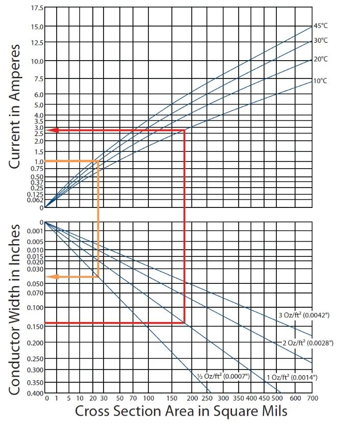
IPC‑2152 nomograph for trace width, current, and temperature rise
Example 1 (red arrow)
- Trace width: 140 mil
- Copper: 1 oz
- Temp rise: 10°C
- Max current ≈ 2.75 A
Example 2 (orange arrow)
- Current: 1 A
- Temp rise: 30°C
- Copper: 0.5 oz → width ≈ 40 mil
- Copper: 1 oz → width ≈ 20 mil
About Maxipcb
Maxipcb empowers innovators to turn cutting-edge technologies into reality.
We offer one-stop solutions for design, simulation, testing, PCB manufacturing, component procurement and SMT assembly, enabling efficient development, rapid deployment and risk control across the full product lifecycle.Serving the world in communications, industrial automation, aerospace, automotive, semiconductor and beyond, we build a safer, more connected future together.
