As electronic frequencies rise and PCBs become denser, crosstalk has become a critical signal integrity and EMC issue.
As electronic frequencies rise and PCBs become denser, crosstalk has become a critical signal integrity and EMC issue.
What is Crosstalk?
Crosstalk is unwanted energy coupling between adjacent traces without physical contact. It occurs in two forms:
- Capacitive (electric field) coupling
- Inductive (magnetic field) coupling
Both types exist simultaneously in real designs and cause signal integrity degradation and EMC test failures.
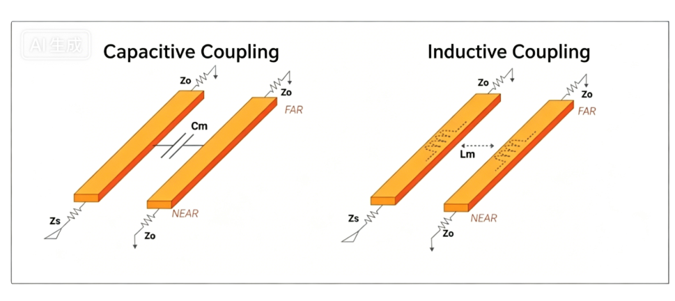
Capacitive and inductive crosstalk models
Harm Caused by Crosstalk
- Reduces signal integrity
- Causes clock/signal delay
- Generates overshoot and transient currents
- Leads to logic errors in chips
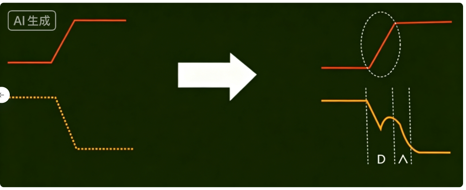
Timing distortion caused by crosstalk
Mechanisms
1. Capacitive Coupling
Parallel traces act like two plates of a
parasitic capacitor.
High‑speed AC signals couple noise to adjacent traces through the electric field.
2. Inductive Coupling
High‑speed current creates a changing magnetic field, inducing noise in nearby traces — similar to a parasitic transformer.
5 Ways to Reduce Crosstalk
-
Follow the 3W Rule
Space traces
3× the trace width apart; reduces crosstalk by ~70%.
Use
10W for sensitive signals.
-
Use a solid ground plane
A continuous inner GND plane absorbs electrical and magnetic noise.
-
Insert ground guard traces
Route GND traces between critical signal groups to block coupling.
-
Minimize vias on high‑speed signals
Vias disrupt impedance and increase crosstalk.
-
Avoid parallel routing
Keep high‑speed and sensitive traces from running parallel over long distances.


