When designing a Printed Circuit Board (PCB), one of the most fundamental issues to consider is how many routing layers, ground planes, and power planes are required to implement the functions required by the circuit.
When designing a Printed Circuit Board (PCB), one of the most fundamental issues to consider is how many routing layers, ground planes, and power planes are required to implement the functions required by the circuit. The determination of the number of routing layers, ground planes, and power planes of a printed circuit board is related to requirements such as circuit function, signal integrity, EMI, EMC, and manufacturing cost.
For most designs, there are many conflicting requirements among factors such as PCB performance requirements, target cost, manufacturing technology, and system complexity. PCB stack-up design is usually a compromise decision after considering various factors. High-speed digital circuits and radio frequency circuits usually adopt multilayer board designs.
1. Layering
The following lists 8 principles that should be noted in stack-up design!
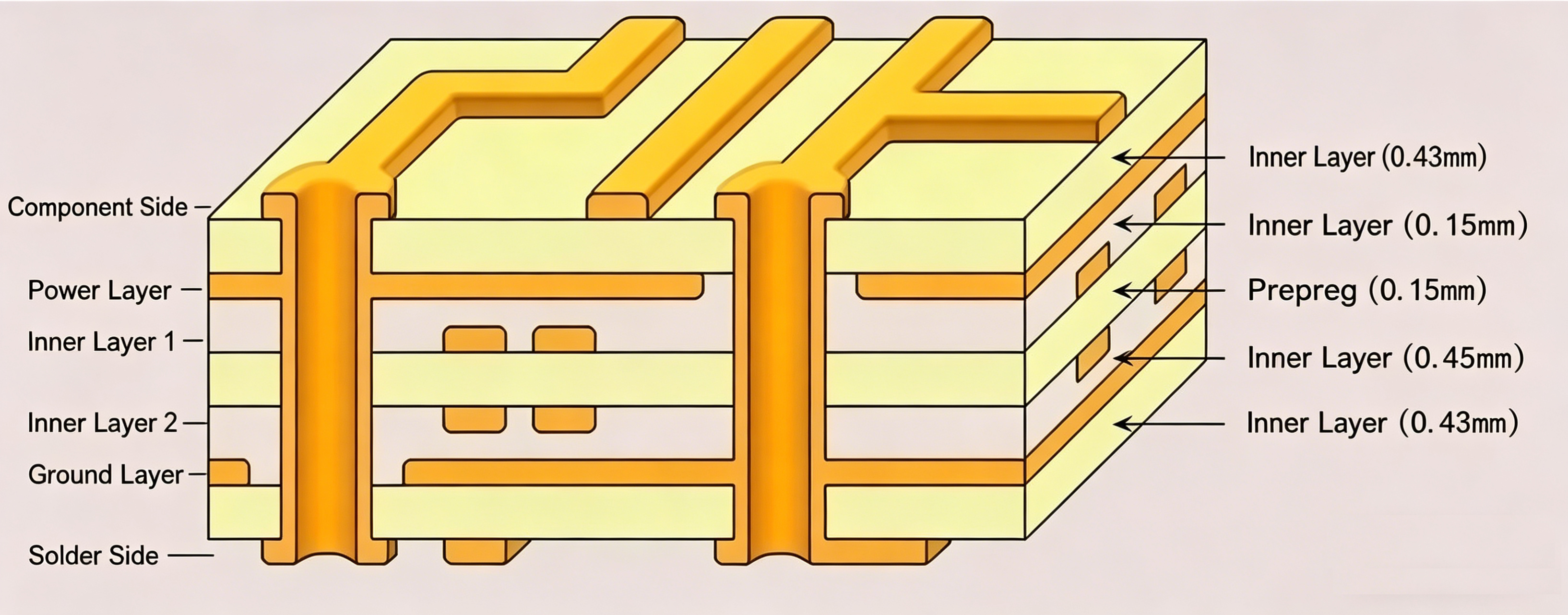
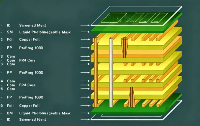
In multilayer PCBs, signal layers (S), power (P) planes, and ground (GND) planes are usually included. Power planes and ground planes are usually solid planes without divisions, which provide a good low-impedance current return path for the currents of adjacent signal traces. Most signal layers are located between these power or ground reference planes, forming symmetrical striplines or asymmetrical striplines.
The top and bottom layers of a multilayer PCB are usually used for placing components and a small number of traces. These signal traces are required not to be too long to reduce direct radiation generated by the traces.
2. Determine the Single Power Reference Plane (Power Plane)
The use of decoupling capacitors is an important measure to solve power integrity. Decoupling capacitors can only be placed on the top and bottom layers of the PCB. The traces, pads, and vias of decoupling capacitors will seriously affect the effect of decoupling capacitors. This requires that the traces connecting the decoupling capacitors should be as short and wide as possible during design, and the wires connected to the vias should also be as short as possible.
For example, in a high-speed digital circuit, decoupling capacitors can be placed on the top layer of the PCB, the second layer can be allocated to the high-speed digital circuit (such as a processor) as the power layer, the third layer as the signal layer, and the fourth layer as the high-speed digital circuit board.
In addition, it is necessary to ensure that the signal traces driven by the same high-speed digital device use the same power layer as the reference plane, and this power layer is the power supply layer for the high-speed digital device.
3. Determine Multiple Power Reference Planes
Multiple power reference planes will be divided into several solid regions with different voltages. If the layer adjacent to the multiple power layers is a signal layer, the signal currents on the nearby signal layer will encounter an undesirable return path, resulting in gaps in the return path. For high-speed digital signals, this unreasonable return path design may cause serious problems, so high-speed digital signal routing should be kept away from multiple power reference planes.
4. Determine Multiple Ground Reference Planes (Ground Planes)
Multiple ground reference planes (ground layers) can provide a good low-impedance current return path and reduce common-mode EMI. The power plane and ground plane should be tightly coupled, and the signal layer should also be tightly coupled with the adjacent reference plane. Reducing the dielectric thickness between layers can achieve this purpose.
5. Reasonably Design Routing Combinations
The two layers spanned by a signal path are called a "routing combination". The best routing combination design is to avoid the return current flowing from one reference plane to another, but from one point (plane) of a reference plane to another point (plane). However, to complete complex routing, inter-layer conversion of traces is inevitable. When converting between signal layers, it is necessary to ensure that the return current can smoothly flow from one reference plane to another. In a design, it is reasonable to take adjacent layers as a routing combination. If a signal path needs to span multiple layers, it is usually not a reasonable design to take it as a routing combination, because a path through multiple layers is not smooth for the return current. Although ground bounce can be reduced by placing decoupling capacitors near vias or reducing the dielectric thickness between reference planes, it is not a good design.
6. Set Routing Directions
On the same signal layer, the direction of most routing should be consistent, and at the same time, it should be orthogonal to the routing direction of adjacent signal layers. For example, the routing direction of one signal layer can be set to the "Y-axis" direction, and the routing direction of another adjacent signal layer can be set to the "X-axis" direction.
7. Adopt an Even-Layer Structure
From the designed PCB stack-ups, it can be found that almost all classic stack-up designs are even-layered rather than odd-layered. This phenomenon is caused by various factors, as follows:
From the manufacturing process of printed circuit boards, it can be understood that all conductive layers in the circuit board are on the core layer, and the material of the core layer is generally a double-sided clad board. When the core layer is fully utilized, the number of conductive layers of the printed circuit board is even.
Even-layer printed circuit boards have cost advantages. Due to one less layer of dielectric and copper cladding, the raw material cost of odd-layer printed circuit boards is slightly lower than that of even-layer printed circuit boards. However, because odd-layer printed circuit boards require an additional non-standard laminated core layer bonding process based on the core layer structure process, the processing cost of odd-layer printed circuit boards is significantly higher than that of even-layer printed circuit boards. Compared with the ordinary core layer structure, adding copper cladding outside the core layer structure will lead to reduced production efficiency and extended production cycle. Before lamination and bonding, the outer core layer also requires additional process treatment, which increases the risk of scratches and incorrect etching on the outer layer. The additional outer layer treatment will significantly increase the manufacturing cost.
After the printed circuit board undergoes the multilayer circuit bonding process, when the inner and outer layers are cooled, different lamination tensions will cause different degrees of bending on the printed circuit board. Moreover, as the thickness of the circuit board increases, the risk of bending of composite printed circuit boards with two different structures increases. Odd-layer circuit boards are prone to bending, while even-layer printed circuit boards can avoid circuit board bending.
In the design, if an odd-layer stack-up occurs, the following methods can be used to increase the number of layers:
- If the designed printed circuit board has an even number of power layers and an odd number of signal layers, the method of adding signal layers can be adopted. The added signal layer will not lead to an increase in cost, but can shorten the processing time and improve the quality of the printed circuit board.
- If the designed printed circuit board has an odd number of power layers and an even number of signal layers, the method of adding a power layer can be adopted. Another simple method is to add a ground layer in the middle of the stack-up without changing other settings, that is, first route according to the odd-layer printed circuit board, and then copy a ground layer in the middle.
- In microwave circuits and mixed dielectric (dielectrics with different dielectric constants) circuits, a blank signal layer can be added near the center of the printed circuit board stack-up, which can minimize stack-up imbalance.
8. Cost Considerations
In terms of manufacturing cost, with the same PCB area, the cost of multilayer circuit boards is definitely higher than that of single-layer and double-layer circuit boards, and the more layers, the higher the cost. However, when considering factors such as realizing circuit functions, miniaturizing circuit boards, and ensuring performance indicators such as signal integrity, EMI, and EMC, multilayer circuit boards should be used as much as possible. Comprehensive evaluation shows that the cost difference between multilayer circuit boards and single- and double-layer circuit boards is not much higher than expected.
About Maxipcb
Maxipcb empowers innovators to turn cutting-edge technologies into reality.
We offer one-stop solutions for design, simulation, testing, PCB manufacturing, component procurement and SMT assembly, enabling efficient development, rapid deployment and risk control across the full product lifecycle.Serving the world in communications, industrial automation, aerospace, automotive, semiconductor and beyond, we build a safer, more connected future together.