In the EMC design considerations for PCBs, layer configuration is the first priority. The number of layers of a single board consists of the number of power layers, ground layers, and signal layers. In EMC design of electronic products, besides component selection and circuit design, proper PCB design is also a critical factor.
In the EMC design considerations for PCBs, layer configuration is the first priority. The number of layers of a single board consists of the number of power layers, ground layers, and signal layers. In EMC design of electronic products, besides component selection and circuit design, proper PCB design is also a critical factor.
The core of PCB EMC design is to minimize the return current area and direct the return path along the designed direction. Layer design serves as the foundation of PCB design. How to optimize PCB layer design to achieve excellent EMC performance?
PCB Layer Design Concept
The concept of EMC planning and design for PCB stack-up is to rationally plan the signal return path, minimize the return area of signals from the reference layer of the single board as much as possible, so as to achieve magnetic flux cancellation or minimization.
1. Reference Layer of Single Board
The reference layer is a complete copper-clad plane layer (power layer or ground layer) inside the PCB adjacent to the signal layer. It mainly has the following functions:
(1) Reduce return current noise: The reference layer provides a low-impedance path for signal layer return current, especially when large current flows in the power distribution system;
(2) Reduce EMI: The existence of the reference layer reduces the area of the closed loop formed by the signal and its return current, thereby lowering EMI;
(3) Reduce crosstalk: It helps control crosstalk between signal traces in high-speed digital circuits. Crosstalk between signal lines can be controlled by adjusting the height of signal lines from the reference layer—the smaller the height, the lower the crosstalk;
(4) Impedance control to prevent signal reflection.
2. Selection of Reference Layer
(1) Both power and ground planes can be used as reference planes and provide certain shielding for internal routing;
(2) Relatively speaking, the power plane has a high characteristic impedance, a large potential difference from the reference level, and relatively high high-frequency interference on the power plane;
(3) From the perspective of shielding, the ground plane is generally grounded and serves as the reference point of the 基准电平,so its shielding effect is far better than that of the power plane;
(4) When selecting a reference plane, the ground plane is preferred, and the power plane is the secondary choice.
Principle of Magnetic Flux Cancellation
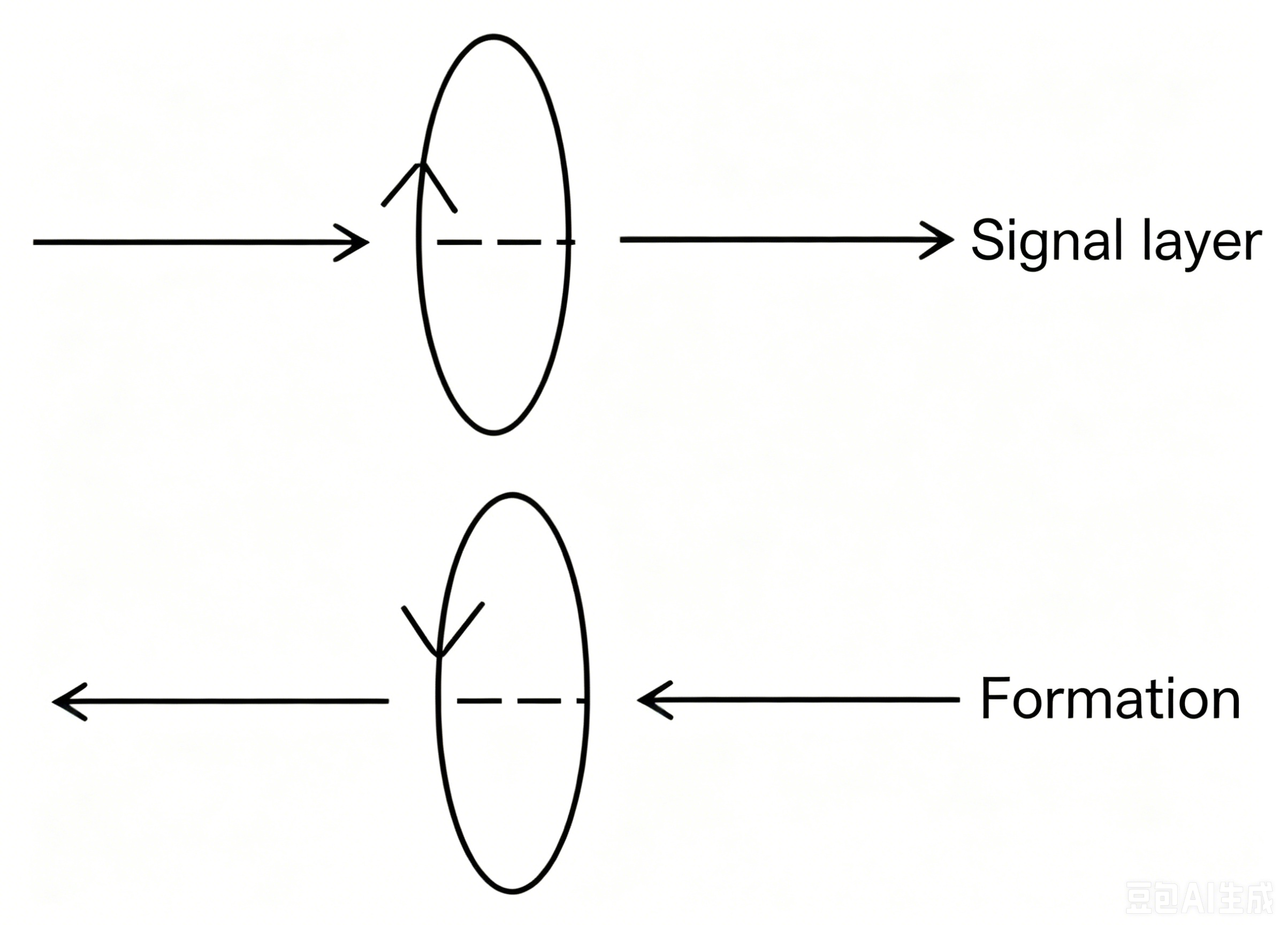
According to Maxwell's equations, all electrical and magnetic interactions between discrete charged bodies or currents are transmitted through the intermediate region between them, whether the intermediate region is a vacuum or a solid material. In PCBs, magnetic flux always propagates in transmission lines. If the RF return path is parallel and close to its corresponding signal path, the magnetic flux on the return path and the signal path are in opposite directions. When they superimpose on each other, the effect of flux cancellation is achieved.
The essence of magnetic flux cancellation is the control of signal return paths. The specific schematic diagram is as follows:
Figure 1: Schematic Diagram of Magnetic Flux Cancellation Principle
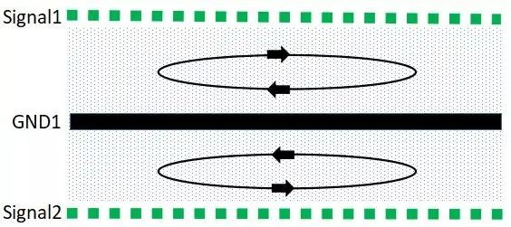
The explanation of magnetic flux cancellation when the signal layer is adjacent to the ground layer using the right-hand rule is as follows:
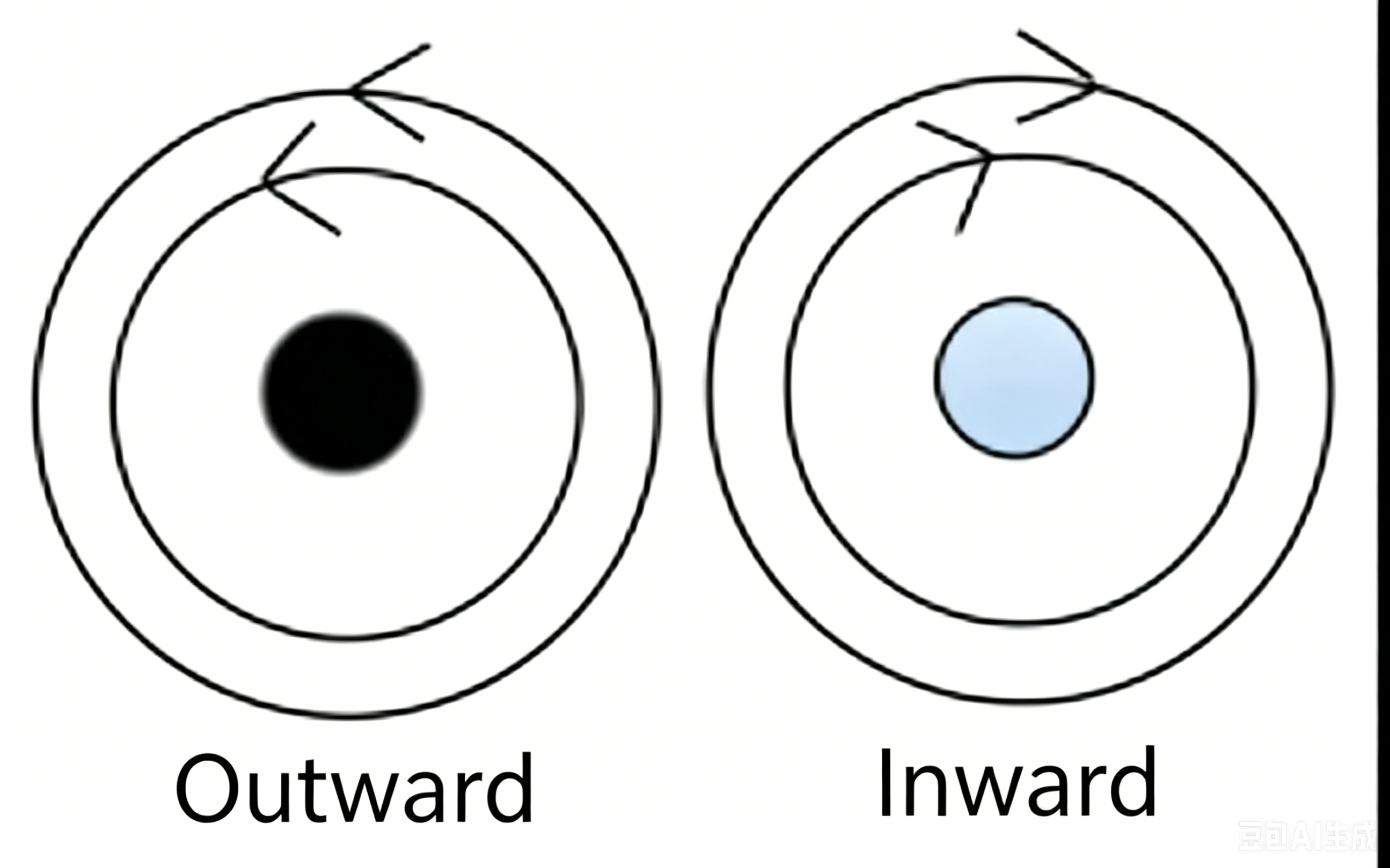
(1) When current flows through a wire, a magnetic field is generated around the wire, and the direction of the magnetic field is determined by the right-hand rule.
(2) When two parallel wires are close to each other, as shown in the figure below, the current in one conductor flows outward, and the current in the other flows inward. If the currents flowing through the two wires are the signal current and its return current respectively, the two currents are equal in magnitude and opposite in direction, so their magnetic fields are also equal in magnitude and opposite in direction, thus canceling each other out.
Design Example of Six-Layer Board
| Scheme |
Power |
Ground |
Signal |
1 |
2 |
3 |
4 |
5 |
6 |
| 1 |
1 |
1 |
4 |
S1 |
G |
S2 |
S3 |
P |
S4 |
| 2 |
1 |
1 |
4 |
S1 |
S2 |
G |
P |
S3 |
S4 |
| 3 |
1 |
2 |
3 |
S1 |
G1 |
S2 |
P |
G2 |
S3 |
| 4 |
1 |
2 |
3 |
S1 |
G1 |
S2 |
G2 |
P |
S3 |
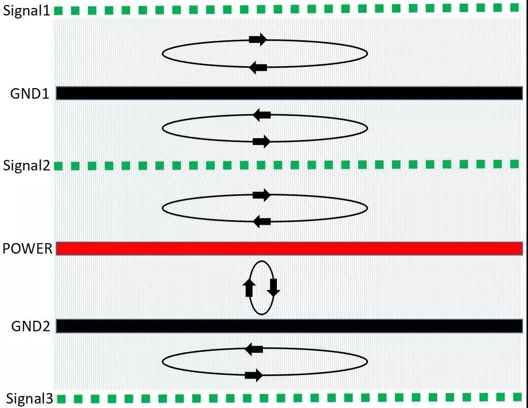
1. For six-layer boards, Scheme 3 is the preferred option
Figure 2: Schematic Diagram of Scheme 3 Stack-Up
Analysis:
(1) Since the signal layers are adjacent to the return reference planes, S1, S2, and S3 are adjacent to the ground planes, achieving effective magnetic flux cancellation. S2 is the preferred routing layer, followed by S3 and S1.
(2) The power plane is adjacent to the GND plane with a small inter-layer distance, achieving good magnetic flux cancellation and low power plane impedance.
(3) The main power and its corresponding ground are arranged on layers 4 and 5. When setting layer thicknesses, increase the spacing between S2-P, reduce the spacing between P-G2 (and correspondingly reduce the spacing between G1-S2), so as to reduce the impedance of the power plane and mitigate the influence of the power supply on S2.
2. Scheme 1 can be adopted when cost requirements are strict
Analysis:
(1) In this structure, the signal layers are adjacent to the return reference planes, and S1 and S2 are close to the ground planes, achieving good magnetic flux cancellation;
(2) The power plane has poor magnetic flux cancellation and high power plane impedance because the return current needs to pass through S3 and S2 to reach the GND plane;
(3) S1 and S2 are the preferred routing layers, followed by S3 and S4.
3. Alternative Scheme 4 for six-layer boards
Figure 3: Schematic Diagram of Scheme 4 Stack-Up

Analysis:
For scenarios with high requirements for local and a small number of signals, Scheme 4 is more suitable than Scheme 3, as it provides an optimized routing layer S2.
4. Scheme 2: Worst EMC Performance
Figure 4: Schematic Diagram of Scheme 2 Stack-Up
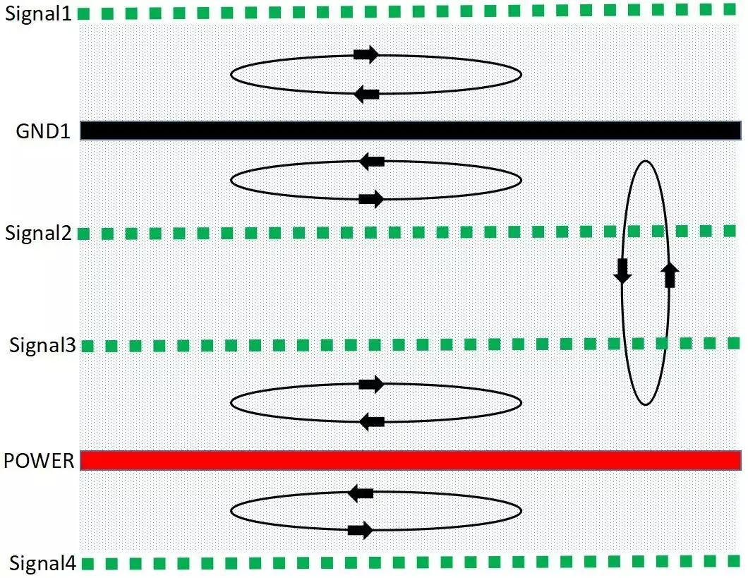
Analysis:
In this structure, S1 is adjacent to S2, S3 is adjacent to S4, and neither S3 nor S4 is adjacent to the ground plane, resulting in poor magnetic flux cancellation effect.
Summary
Specific principles for PCB layer design:
(1) A complete ground plane is placed under the component side and solder side for shielding;
(2) Avoid direct adjacency of two signal layers as much as possible;
(3) All signal layers shall be adjacent to the ground plane as much as possible;
(4) Key signal routing layers such as high-frequency, high-speed, and clock signals shall have an adjacent ground plane.
About Maxipcb
Maxipcb empowers innovators to turn cutting-edge technologies into reality.
We offer one-stop solutions for design, simulation, testing, PCB manufacturing, component procurement and SMT assembly, enabling efficient development, rapid deployment and risk control across the full product lifecycle.Serving the world in communications, industrial automation, aerospace, automotive, semiconductor and beyond, we build a safer, more connected future together.