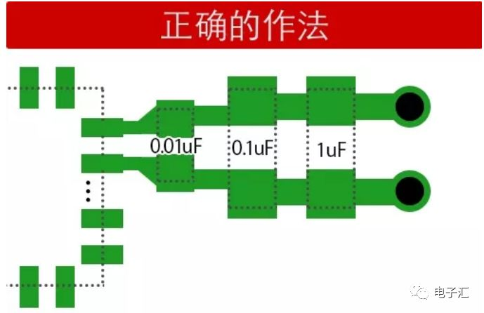
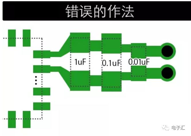
For IC circuits sensitive to noise, to achieve a better filtering effect, multiple capacitors with different capacitance values are usually used in parallel to cover a wider filtering frequency range. For example, parallel connection of 1μF, 100nF and 10nF capacitors at the power input terminal of an IC can deliver better filtering performance. The question now arises: when laying out these capacitors of different specifications in PCB design, should the power path go through the large capacitor first, then the small capacitor, and finally into the IC, or through the small capacitor first, then the large capacitor, and then into the IC?
As we know, in practical applications, a capacitor is not just an ideal capacitor C, but also has Equivalent Series Resistance (ESR) and Equivalent Series Inductance (ESL). The simplified model of an actual capacitor is shown in the figure below.
An important characteristic index that needs attention when using capacitors in high-speed circuits is the self-resonant frequency of the capacitor. The formula for the self-resonant frequency of a capacitor is expressed as:
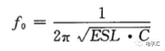
The self-resonant frequency point is the dividing line that distinguishes whether a capacitor exhibits capacitive or inductive characteristics. Below the resonant frequency, the capacitor behaves as a capacitor; above the resonant frequency, the capacitor behaves as an inductor. The capacitor has a low impedance only near the self-resonant frequency point. Therefore, an actual decoupling capacitor has a certain operating frequency range, and it can only exert an excellent decoupling effect in the frequency band near its self-resonant frequency point. Special attention must be paid to this point when using capacitors for power supply decoupling.
The characteristic impedance of a capacitor can be expressed as:
\(Z=ESR+j(\omega L-\frac{1}{\omega C})\)It can be seen that the self-resonant point of a large capacitor (1μF) is lower than that of a small capacitor (10nF). Correspondingly, large capacitors are less sensitive to the parasitic equivalent series inductance ESL generated on the mounted PCB than small capacitors.
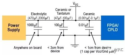
Therefore, small capacitors should be placed as close to the power supply pins of the IC as possible, while the placement of large capacitors is relatively more flexible. However, all capacitors should be placed as close to the IC as possible; if the distance exceeds the decoupling radius, they will lose their decoupling effect. The correct and incorrect methods are shown in the figures below.
The overall circuit schematic is as follows:
 About Maxipcb
Maxipcb empowers innovators to turn cutting-edge technologies into reality.
We offer one-stop solutions for design, simulation, testing, PCB manufacturing, component procurement and SMT assembly, enabling efficient development, rapid deployment and risk control across the full product lifecycle.Serving the world in communications, industrial automation, aerospace, automotive, semiconductor and beyond, we build a safer, more connected future together.