A student came to me a few days ago, saying that the gain of his RF front-end module dropped by 3dB at high temperatures. His supervisor asked him to implement temperature compensation, but he did not know whether to use a thermistor or a digital attenuator. Honestly, I made the same mistake back in the day. Today I will share my experience with you.
A student came to me a few days ago, saying that the gain of his RF front-end module dropped by 3dB at high temperatures. His supervisor asked him to implement temperature compensation, but he did not know whether to use a thermistor or a digital attenuator. Honestly, I made the same mistake back in the day. Today I will share my experience with you.
Temperature drift in RF circuits is a long-standing problem. It is easy to understand — most parameters of RF devices are strongly temperature-dependent, such as PA gain, filter insertion loss, and LNA noise figure. These indicators drift as the ambient temperature changes. The temperature drift problem is particularly prominent in wide-temperature applications such as automotive electronics and outdoor base stations.
In my experience, there are two core approaches to temperature compensation: one is passive compensation, using temperature-sensitive devices (such as thermistors) for automatic adjustment; the other is active compensation, using MCU or digital control methods for real-time adjustment. These two approaches correspond to the thermistor solution and the digital attenuator solution.
Thermistor Solution: Simple and Reliable, but Limited Accuracy
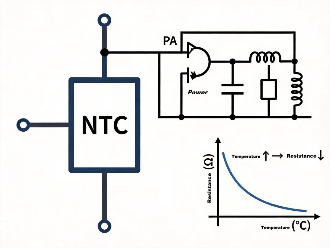
Let’s start with the thermistor solution. The principle is simple: utilize the temperature-dependent resistance characteristic of a thermistor, and integrate it into the circuit as part of the feedback or bias network. For example, a negative temperature coefficient (NTC) thermistor is connected in series in the PA bias circuit. As temperature rises, resistance decreases, adjusting the PA gate voltage to compensate for gain drop. The biggest advantage of this solution is that no additional control circuit is required; it is an open-loop compensation with high reliability and benign failure modes.
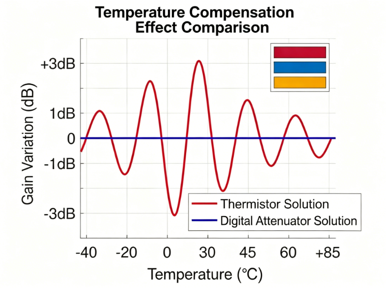
However, the thermistor solution has obvious limitations. First, accuracy is limited — the resistance change of a thermistor is a physical property. Manufacturers provide a B-value (thermal coefficient), but the actual compensation effect depends on the matching of your circuit design. Often, the gain is well-tuned at 25℃, but the curve distorts at high temperatures (60℃) and low temperatures (-40℃), requiring repeated iterations. Second, flexibility is poor. Once the circuit is finalized, adjusting the compensation curve requires hardware resistor changes, leading to long debugging cycles and high costs.
Digital Attenuator Solution: Precise and Flexible, but Increased Complexity
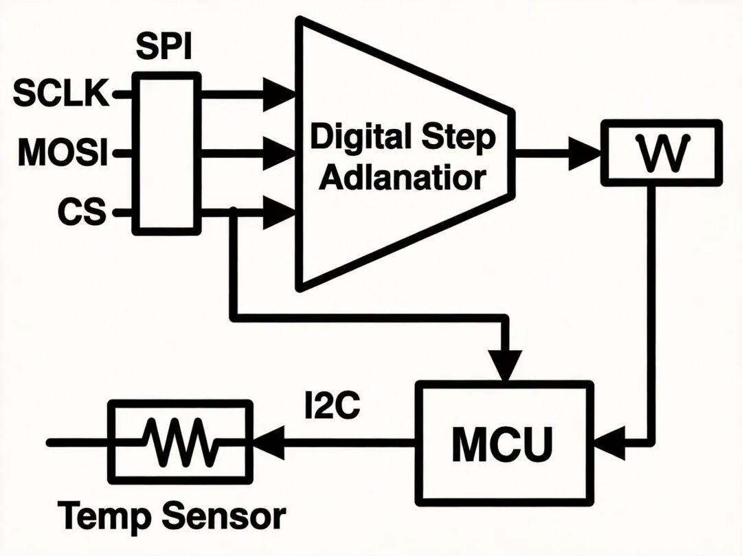
Next is the digital attenuator solution. The idea is more straightforward — use a digital attenuator chip with an integrated temperature sensor, and adjust the attenuation in real time with an MCU via lookup table (LUT) or PID algorithm. Mature digital step attenuators are available from vendors such as Renaissance and Peregrine, supporting SPI control with step accuracy down to 0.25dB or finer.
The digital attenuator solution offers high precision and strong flexibility. You can program a temperature-attenuation lookup table (LUT) in firmware for fine-grained compensation across different frequency bands and operating points. Another benefit is that the compensation algorithm can be upgraded remotely without hardware modifications.
On the downside, complexity increases. Additional MCU resources, a temperature sensor, firmware compensation logic, and reliable SPI timing are required. System-level failure points rise, potentially reducing reliability. Furthermore, digital attenuators themselves suffer from temperature drift! Yes, the internal switch and resistor networks are also temperature-sensitive, so you must check the temperature coefficient parameters in the datasheet during component selection.
Temperature Compensation Performance Comparison
Interestingly, the two solutions are not mutually exclusive. In a previous project, we used a thermistor for coarse PA compensation and a digital attenuator for fine compensation, achieving better hierarchical compensation results. This combined strategy is common in high-precision phased array radars and instruments.
In my experience, follow this selection guideline:
- For consumer electronics or industrial products with high cost and reliability requirements and large volumes, the thermistor solution is preferred.
- For scientific research or military products requiring flexible compensation strategies, or systems already equipped with MCU resources, the digital attenuator solution is more suitable.
Finally, a critical layout detail: whether using a thermistor or digital attenuator, packaging and layout are vital.
- Thermistors must be placed as close as possible to the compensated device to maintain good thermal coupling.
- Control and power traces of digital attenuators must be properly filtered to avoid introducing interference.
To summarize: The thermistor solution is simple, reliable, and low-cost, suitable for high-volume industrial products. The digital attenuator solution is precise and flexible, ideal for high-end applications requiring fine compensation. The two can also be combined for hierarchical temperature compensation.
That’s all for today. If you are working on a temperature compensation project and have specific questions, feel free to leave a comment. See you next time.
About Maxipcb
Maxipcb empowers innovators to turn cutting-edge technologies into reality.
We offer one-stop solutions for design, simulation, testing, PCB manufacturing, component procurement and SMT assembly, enabling efficient development, rapid deployment and risk control across the full product lifecycle.Serving the world in communications, industrial automation, aerospace, automotive, semiconductor and beyond, we build a safer, more connected future together.