Recently, while debugging a 5G millimeter-wave array antenna project, the beam could never be aligned correctly. After checking the code, algorithms, and phase shifter configurations for a long time, it turned out that the two RF traces differed by less than 1 millimeter.
Recently, while debugging a 5G millimeter-wave array antenna project, the beam could never be aligned correctly. After checking the code, algorithms, and phase shifter configurations for a long time, it turned out that the two RF traces differed by less than 1 millimeter.
It sounds absurd, but this issue is extremely common in the RF field. Today, I will explain why a tiny difference in trace length can completely disable an entire beamforming system.
First, Understand How Beamforming Works
The principle of beamforming is simply wave interference. When multiple antenna elements transmit signals simultaneously, each signal superimposes in space. If all signals are in phase, they strengthen each other in a certain direction to form the desired main beam; if out of phase, they cancel each other out in some directions.
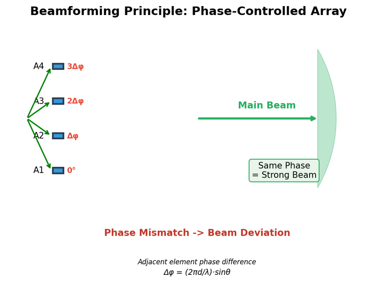
The core formula of a phased array antenna is as follows:
Δφ = (2πd/λ) × sinθ
Where Δφ is the phase difference between adjacent antenna elements, d is the element spacing, λ is the signal wavelength, and θ is the beam pointing angle. Engineers adjust the phase shifters to control Δφ, thereby changing θ to point the beam in any desired direction.
The problem is: if the hardware traces themselves are unequal in length, adjusting the phase shifters is useless. Because the signal already incurs an additional phase offset from the trace length difference before reaching the antenna element.
How Much Impact Does a Trace Length Difference Cause?
The key formula for this problem is simple:
Phase Difference = 360° × (Length Difference) / Wavelength
In other words, a length difference of one wavelength produces a phase difference of 360°, which is one full cycle.
Let me calculate practical examples for the most common 5G NR frequency bands:
- n78 band (3.5GHz): Wavelength ≈ 85.7mm. A 1mm trace difference causes a phase difference of approximately 4.2°. It sounds small? But for a 64-element phased array antenna, this error accumulates, and the main beam can deviate by several degrees.
- n257 band (28GHz): Wavelength ≈ 10.7mm. A 1mm length difference directly causes a 33.6° phase difference! The beam can easily deviate by more than ten degrees.
- n260 band (39GHz): Wavelength is only 7.7mm. A 1mm difference results in a 46.7° phase difference—nearly half a cycle. In this case, beamforming is essentially ineffective.
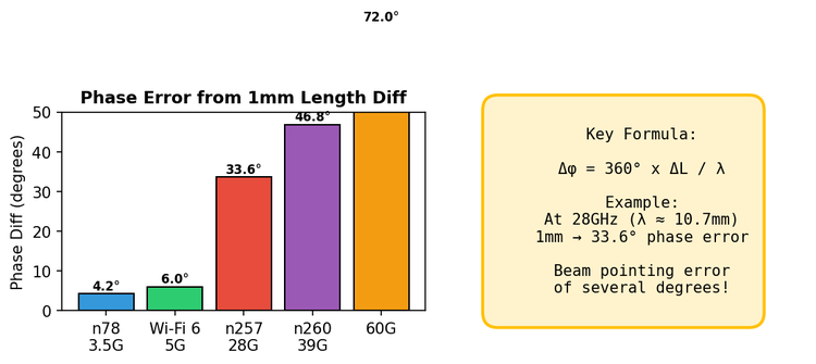
Isn’t that terrifying? One millimeter is a negligible error in daily perception, but in the RF field, it can be the critical point for performance collapse.
Electrical Length vs. Physical Length: A Common Pitfall Even for Experienced Engineers
In PCB design, many beginners make the mistake of only looking at physical length, not electrical length.
Physical length is the distance measured with a ruler. But electrical length is what truly determines signal delay.
Electrical length is affected by several factors:
- Dielectric constant of the medium (εr): For common FR-4, εr ≈ 4.4, and the signal propagation speed is only about 60% of that in a vacuum. That is, a 10mm trace on FR-4 has a much longer electrical length than in air.
- Trace structure: Microstrip lines and striplines have different propagation speeds. Microstrip lines run on the surface, with air on one side and the substrate on the other; striplines are sandwiched between two ground planes, with more uniform dielectric influence.
- Vias and corners: Each via introduces an equivalent length of approximately 0.5–2mm. 90° right-angle corners also add extra electrical length, which is small but cannot be ignored at high frequencies.
The correct approach is to account for all factors and ensure the electrical lengths of all RF paths are equal. This is true length matching.
Practical Case: Wi-Fi 6E Router Antenna Array
I previously worked on a Wi-Fi 6E (6GHz band) router project with an 8×8 MIMO antenna array. The goal was to dynamically form beams toward different client directions.
After the first batch of prototypes, OTA testing found a deviation in the main beam pointing. The design was supposed to radiate toward 0°, but the actual measurement deviated by approximately 8°.
Troubleshooting process:
- Check phase shifter configuration – no issues.
- Check baseband algorithm – no issues.
- Finally, measure the phase of each RF path with a Vector Network Analyzer (VNA) – sure enough, two adjacent paths had a phase difference of nearly 30°.
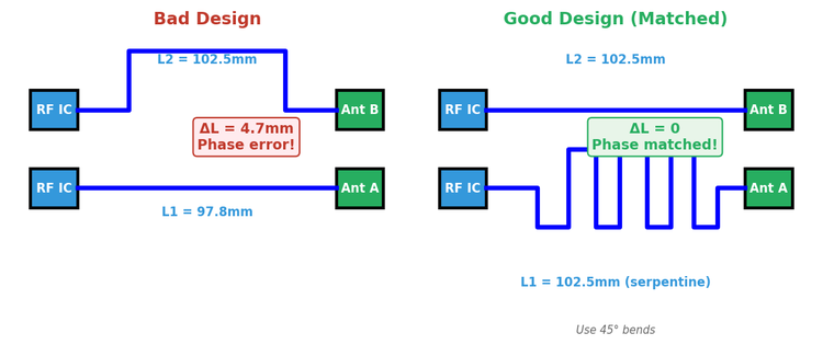
Reviewing the PCB layout, it turned out that between the RF chip and the antenna array, one trace ran a straight 100mm, while the other detoured around an inductor, resulting in an actual length of only 97.8mm.
A 2.2mm difference corresponds to a phase difference of approximately 15.8° at 6GHz (wavelength 50mm). Coupled with the ordinary FR-4 substrate (poor εr consistency across regions), the actual phase difference was closer to 30°.
The solution was simple: use serpentine routing to lengthen the shorter trace, making the electrical lengths of the two paths identical. After redesign and retesting, the beam pointing accuracy recovered to within ±1°.
Having covered the problems, the key is how to solve them. I summarize several practical methods:
-
Use professional impedance calculation tools
Before routing RF traces, use tools such as Polar SI9000 or ADS LineCalc to calculate the trace width corresponding to the target impedance (usually 50Ω). Then design length matching based on this width.
Do not estimate by experience. Especially in the millimeter-wave band, a 0.05mm difference in trace width can shift impedance by 10Ω.
-
Use the length-matching function of EDA software
Mainstream EDA tools such as Altium, Cadence, and KiCad have length-matching functions. Set a length tolerance (e.g., ±0.5mm), and the tool automatically generates serpentine traces for compensation.
Note that serpentine routing introduces parasitic effects. Use 45° angles instead of 90° at bends, and maintain sufficient trace spacing to avoid coupling.
-
Consider temperature and aging factors
Many people overlook this: the dielectric constant of the substrate changes with temperature. If your product operates over a wide temperature range (e.g., automotive or outdoor equipment), phase stability becomes a problem.
In this case, use high-stability substrates with low dielectric constant, such as RO4003C and Rogers 4350. They are more expensive than FR-4 but worthwhile for high-performance applications.
-
Reserve debugging margin
During design, reserve positions for adjustable components in the RF chain. For example, series microstrip stubs (length can be fine-tuned with solder or a soldering iron), or positions for adjustable capacitors/inductors for phase fine-tuning.
Deviations may still occur after mass production; reserved debugging margin is critical.
Practical Impact of Beam Pointing Deviation
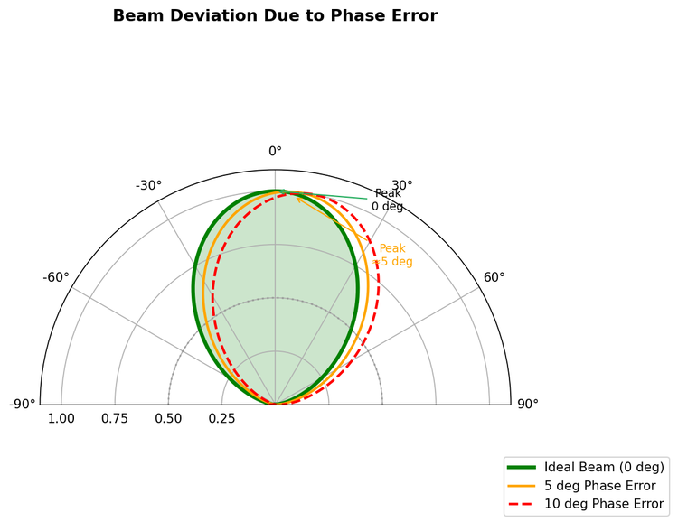
The figure above shows the impact of different phase errors on beam pointing. A 5° phase error significantly shifts the main beam peak, and a 10° error completely changes the beam direction.
What problems does this cause in real systems?
- Degraded end-user signal quality: the base station is nearby, but the phone cannot get a full signal.
- High handover failure rate: the target cell’s beam does not cover your location.
- Reduced system capacity: misaligned beams waste energy.
Length Accuracy Requirements by Frequency Band
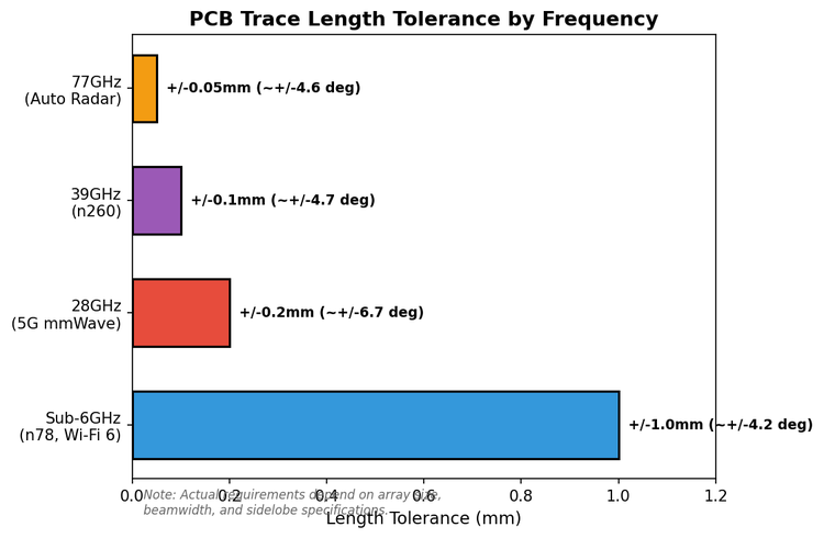
Finally, a reference table based on practical experience from peers and me:
| Application Scenario |
Length Matching Tolerance |
Corresponding Phase Error |
| Sub-6GHz band (e.g., 5G n78, Wi-Fi 6) |
Within ±1mm |
Approx. 4–5° |
| 28GHz band (5G mmWave) |
Within ±0.2mm |
Approx. 7° |
| 39GHz and above bands |
Within ±0.1mm |
Approx. 5° |
| Phased array radar systems |
A few hundredths of a millimeter |
Usually within ±1° |
This accuracy requirement is extremely high, requiring strict control over PCB processing and soldering. Such levels typically use phase-stable cables instead of PCB traces, combined with calibration algorithms for compensation.
Closing Thoughts
RF design is such that an inconspicuous detail can be the difference between meeting performance specs and total failure. A "tiny" trace length difference sounds trivial, but in a beamforming system, it is amplified by the antenna array, resulting in beam pointing deviation, gain reduction, and sidelobe degradation.
My experience: spending one extra hour checking length matching in the design phase avoids many pitfalls in debugging. The satisfaction of seeing the near-field test beam pattern point exactly where you want it in the anechoic chamber is unparalleled.
About Maxipcb
Maxipcb empowers innovators to turn cutting-edge technologies into reality.
We offer one-stop solutions for design, simulation, testing, PCB manufacturing, component procurement and SMT assembly, enabling efficient development, rapid deployment and risk control across the full product lifecycle.Serving the world in communications, industrial automation, aerospace, automotive, semiconductor and beyond, we build a safer, more connected future together.