
During PCB design, splitting the power plane or ground plane will lead to plane discontinuity. In this case, when a signal is routed, its reference plane may jump from one power plane to another. This phenomenon is called signal split-plane crossing.
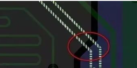
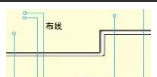
Schematic diagram of split-plane crossing
Split-plane crossing may not matter for low-speed signals, but in high-speed digital signal systems, high-speed signals use the reference plane as the return path, i.e., the return current path. When the reference plane is discontinuous, the following adverse effects will occur:
-
It will cause impedance discontinuity of the trace;
-
It can easily cause crosstalk between signals;
-
It will cause reflections between signals;
-
It increases the current loop area and the loop inductance, making the output waveform prone to oscillation;
-
It increases radiated interference into space and makes the circuit more susceptible to spatial magnetic fields;
-
It increases the possibility of magnetic field coupling with other circuits on the board;
-
The high-frequency voltage drop on the loop inductance forms a common-mode radiation source and generates common-mode radiation through external cables.
Therefore, PCB routing should be as close as possible to a plane and should avoid split-plane crossing. If split-plane crossing is unavoidable or the trace cannot be close to the power/ground plane, these situations are only allowed for low-speed signal lines.
Handling Split-Plane Crossing in Design
If split-plane crossing inevitably occurs in PCB design, how should it be handled? In this case, the split needs to be stitched to provide a shorter return current path for the signal. Common handling methods include adding stitching capacitors and trace bridging.
Stitching Capacitor
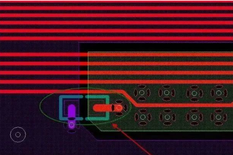
Usually, a 0402 or 0603 ceramic capacitor is placed at the signal split-plane crossing position. The capacitance is 0.01 μF or 0.1 μF. If space permits, multiple such capacitors can be added.
At the same time, ensure that the signal line is within 200 mil of the stitching capacitor; the smaller the distance, the better. The networks at the two ends of the capacitor correspond to the networks of the reference plane that the signal passes through. See the networks connected to the two ends of the capacitor in the figure below—the two different networks highlighted in two colors:
Trace Bridging
A common method is to perform “ground enclosing” on the signal that crosses the split on the signal layer. The enclosing trace may also enclose signal lines of other networks. This “ground enclosing” trace should be as thick as possible. See the figure below for this handling method.
High-Speed Signal Routing Techniques
Multilayer Routing
High-speed signal routing circuits often have high integration and high routing density. Using multilayer boards is both necessary for routing and an effective means of reducing interference.
Reasonable selection of the number of layers can greatly reduce PCB size, make full use of intermediate layers for shielding, better achieve local grounding, effectively reduce parasitic inductance, effectively shorten signal transmission length, and greatly reduce cross-interference between signals.
Fewer Lead Bends Are Better
The fewer bends in the leads between device pins of high-speed circuits, the better.
For high-speed signal routing, the leads should preferably be completely straight. If a turn is required, use a 45° bend or an arc bend. In low-frequency circuits, this requirement is only used to improve the adhesion strength of copper foil.
In high-speed circuits, however, meeting this requirement can reduce external emission and mutual coupling of high-speed signals and reduce signal radiation and reflection.
Shorter Leads Are Better
The shorter the leads between device pins of high-speed signal routing circuits, the better.
The longer the lead, the larger the distributed inductance and distributed capacitance it introduces, which greatly affects the passage of high-frequency signals in the system. It also changes the characteristic impedance of the circuit, causing reflection, oscillation, and so on.
Fewer Layer Transitions Are Better
The fewer layer transitions of leads between device pins of high-speed circuits, the better.
“Fewer layer transitions of leads” means fewer vias used when connecting components.
It is measured that one via can introduce about 0.5 pF of distributed capacitance, significantly increasing circuit delay. Reducing the number of vias can significantly improve speed.
Pay Attention to Parallel Crosstalk
High-speed signal routing should pay attention to the “crosstalk” introduced by close parallel routing of signal lines. If parallel distribution cannot be avoided, place a large-area “ground” on the opposite side of the parallel signal lines to greatly reduce interference.
Avoid Branches and Stubs
High-speed signal routing should try to avoid branches or the formation of stubs.
Stubs greatly affect impedance and can cause signal reflection and overshoot, so we usually should avoid stubs and branches in design.
Use daisy-chain routing to reduce the impact on signals.
Route Signal Lines on Inner Layers as Much as Possible
High-frequency signal lines routed on the surface layer are prone to generating large electromagnetic radiation and are also susceptible to external electromagnetic radiation or interference.
Route high-frequency signal lines between power and ground lines. Through the absorption of electromagnetic waves by the power and ground layers, the generated radiation will be greatly
reduced.