In practical research, we have summarized that there are four main types of interference: power supply noise, transmission line interference, coupling, and electromagnetic interference (EMI). By analyzing various interference problems in high-frequency PCBs and combining practical work experience, effective solutions are proposed.
In practical research, we have summarized that there are four main types of interference: power supply noise, transmission line interference, coupling, and electromagnetic interference (EMI). By analyzing various interference problems in high-frequency PCBs and combining practical work experience, effective solutions are proposed.
I. Power Supply Noise
In high-frequency circuits, the noise carried by the power supply has a particularly significant impact on high-frequency signals. Therefore, a low-noise power supply is required first. Here, a clean ground is as important as a clean power supply. Why? The power supply characteristics are shown in Figure 1. Obviously, the power supply has a certain impedance, and the impedance is distributed throughout the power supply, so noise will also be superimposed on the power supply. Therefore, we should minimize the impedance of the power supply, and it is best to have dedicated power planes and ground planes. In high-frequency circuit design, designing the power supply in the form of layers is much better than in the form of buses in most cases, so that the loop can always follow the path of minimum impedance. In addition, the power plane must provide a signal return path for all signals generated and received on the PCB, which can minimize the signal loop and thus reduce noise, a point often overlooked by low-frequency circuit designers.
The methods to eliminate power supply noise in PCB design are as follows:
- Pay attention to vias on the board: Vias require etched openings on the power plane to leave space for vias to pass through. If the openings on the power plane are too large, the signal loop will inevitably be affected, forcing the signal to detour, increasing the loop area and noise. At the same time, if some signal lines are concentrated near the openings and share this section of the loop, common impedance will cause crosstalk.
- Sufficient ground lines are required for connecting wires: Each signal needs its own dedicated signal return path, and the loop area of the signal and the return path should be as small as possible, that is, the signal and the return path should be parallel.
- Separate analog and digital power supplies: High-frequency devices are generally very sensitive to digital noise, so the two must be separated and connected together at the entrance of the power supply. If the signal needs to cross both analog and digital parts, a return path can be placed at the signal crossing point to reduce the loop area.
- Avoid overlapping of separate power supplies between different layers: Otherwise, circuit noise can easily couple through parasitic capacitance.
- Isolate sensitive components: Such as PLL.
- Place power lines: To reduce the signal loop, place power lines next to signal lines to achieve noise reduction.
II. Transmission Lines
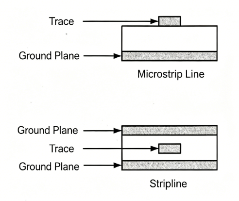
There are only two types of transmission lines in PCBs: striplines and microstrip lines. The biggest problem with transmission lines is reflection, which causes many problems. For example, the load signal will be the superposition of the original signal and the echo signal, increasing the difficulty of signal analysis; reflection will cause return loss, and its impact on the signal is as serious as that caused by additive noise interference:
- The signal reflected back to the signal source will increase the system noise, making it more difficult for the receiver to distinguish between noise and signal.
- Any reflected signal will basically degrade the signal quality and change the shape of the input signal. In principle, the main solution is impedance matching (for example, the interconnection impedance should be very well matched to the system impedance), but sometimes impedance calculation is troublesome, and you can refer to some transmission line impedance calculation software.
The methods to eliminate transmission line interference in PCB design are as follows:
(a) Avoid impedance discontinuities in transmission lines. Impedance discontinuities are points where the transmission line changes abruptly, such as right-angle bends, vias, etc., which should be avoided as much as possible. Methods include: avoiding right-angle bends in routing, using 45° angles or arcs as much as possible, and large bends are also acceptable; using as few vias as possible, because each via is an impedance discontinuity point, and outer layer signals should avoid passing through inner layers, and vice versa.
(b) Do not use stubs. Because any stub is a noise source. If the stub is short, it can be terminated at the end of the transmission line; if the stub is long, it will generate large reflections with the main transmission line as the source, complicating the problem, so it is recommended not to use it.
III. Coupling
- Common impedance coupling: It is a common coupling channel, that is, the interference source and the interfered equipment often share some conductors (such as loop power supplies, buses, common grounds, etc.).
- Field common-mode coupling: It will cause the radiation source to induce common-mode voltage on the loop formed by the interfered circuit and the common reference plane. If the magnetic field is dominant, the value of the common-mode voltage generated in the series ground loop is Vcm = -(△B/△t) * Area (where △B = the change in magnetic induction intensity). If it is an electromagnetic field and its electric field value is known, the induced voltage is: Vcm = (LhFE)/48. This formula applies to L (m) below 150MHz. Above this limit, the calculation of the maximum induced voltage can be simplified to: Vcm = 2h*E.
- Differential-mode field coupling: Refers to the direct radiation being inductively received by wire pairs or leads on the circuit board and their loops. If the two wires are kept as close as possible, this coupling will be greatly reduced, so the two wires can be twisted together to reduce interference.
- Line-to-line coupling (crosstalk): It can cause undesired coupling between any lines equal to parallel circuits, which will seriously damage the system performance in severe cases. Its types can be divided into capacitive crosstalk and inductive crosstalk. The former is because the parasitic capacitance between lines allows the noise on the noise source to couple to the noise receiving line through current injection; the latter can be imagined as the coupling of signals between the primary and secondary sides of an undesired parasitic transformer. The magnitude of inductive crosstalk depends on the proximity of the two loops, the size of the loop area, and the impedance of the affected load.
- Power line coupling: It refers to that after AC or DC power lines are subjected to electromagnetic interference, the power lines transmit these interferences to other equipment.
The methods to eliminate crosstalk in PCB design are as follows:
- The magnitude of both types of crosstalk increases with the increase of load impedance, so appropriate termination should be performed on signal lines sensitive to interference caused by crosstalk.
- Increasing the distance between signal lines as much as possible can effectively reduce capacitive crosstalk. Conduct ground plane management, provide spacing between wirings (for example, isolate active signal lines from ground lines, especially between signal lines with state transitions and ground), and reduce lead inductance.
- Inserting a ground line between adjacent signal lines can also effectively reduce capacitive crosstalk, and this ground line needs to be connected to the ground layer every 1/4 wavelength.
- For inductive crosstalk, minimize the loop area, and eliminate the loop if possible.
- Avoid signal sharing loops.
- Pay attention to signal integrity: Designers should implement termination during soldering to solve signal integrity. Designers adopting this method can focus on the microstrip length of the copper foil used for shielding to obtain good signal integrity performance. For systems using dense connectors in communication structures, designers can use a PCB for termination.
IV. Electromagnetic Interference (EMI)
As speed increases, EMI will become more and more serious and manifest in many aspects (such as electromagnetic interference at interconnections). High-speed devices are particularly sensitive to this, and will receive high-speed false signals as a result, while low-speed devices will ignore such false signals.
The methods to eliminate electromagnetic interference in PCB design are as follows:
- Reduce loops: Each loop is equivalent to an antenna, so we need to minimize the number of loops, the area of loops, and the antenna effect of loops. Ensure that there is only one unique loop path for signals between any two points, avoid artificial loops, and use power planes as much as possible.
- Filtering: Filtering can be adopted on both power lines and signal lines to reduce EMI. There are three methods: decoupling capacitors, EMI filters, and magnetic components.
- Shielding. Due to space limitations and the large number of articles discussing shielding, no specific introduction is given here.
- Reduce the speed of high-frequency devices as much as possible.
- Increasing the dielectric constant of the PCB board can prevent high-frequency parts such as transmission lines close to the board from radiating outward; increasing the thickness of the PCB board and minimizing the thickness of the microstrip line can prevent the overflow of electromagnetic lines and also prevent radiation.
At this point, we can summarize the following principles that should be followed in high-frequency PCB design:
- Unified and stable power supply and ground.
- Careful routing and proper termination can eliminate reflections.
- Careful routing and proper termination can reduce capacitive and inductive crosstalk.
- Noise suppression is required to meet EMC requirements.
About Maxipcb
Maxipcb empowers innovators to turn cutting-edge technologies into reality.
We offer one-stop solutions for design, simulation, testing, PCB manufacturing, component procurement and SMT assembly, enabling efficient development, rapid deployment and risk control across the full product lifecycle.Serving the world in communications, industrial automation, aerospace, automotive, semiconductor and beyond, we build a safer, more connected future together.