The main characteristics of a flexible printed circuit board (FPC) compared with a standard rigid PCB are its thinness, light weight, and flexibility. Since the cost of FPCs is much higher than that of PCBs, manufacturers generally do not design FPCs into their products unless necessary. Because of this high cost, special attention must be paid to its limitations and design considerations during the design phase.
The main characteristics of a flexible printed circuit board (FPC) compared with a standard rigid PCB are its thinness, light weight, and flexibility. Since the cost of FPCs is much higher than that of PCBs, manufacturers generally do not design FPCs into their products unless necessary. Because of this high cost, special attention must be paid to its limitations and design considerations during the design phase.
This information was originally provided by a flexible board (FPC/Flex Cable) manufacturer, and was only available in paper form at the time. I later spent some time organising and illustrating it here, so that I and others who need it can refer to it. I personally think these design guidelines can serve as a useful reference for many designers. Some of these requirements are closely related to manufacturing process capabilities, while others relate to reliability and quality.
1. Dimensional Relationships Between Through Holes, Cover Film, and Land Patterns in FPC Design
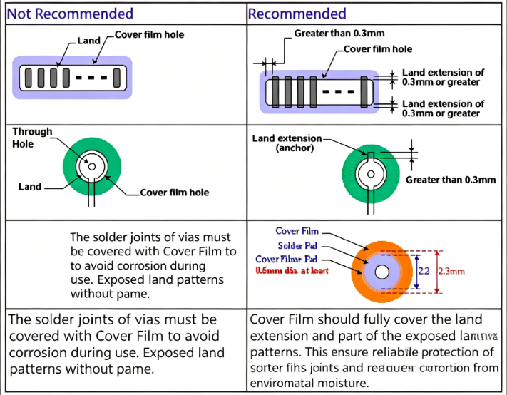
When designing flexible circuits, the dimensional relationships between through holes, the cover film openings, and the land patterns must be carefully controlled. The cover film opening should be slightly larger than the land pattern to ensure proper clearance, while the through‑hole pad dimensions must meet the manufacturer's minimum requirements for reliable plating and mechanical strength. These dimensions affect both the manufacturability and the long‑term reliability of the flexible board.
2. Recommendations for Trace Geometry
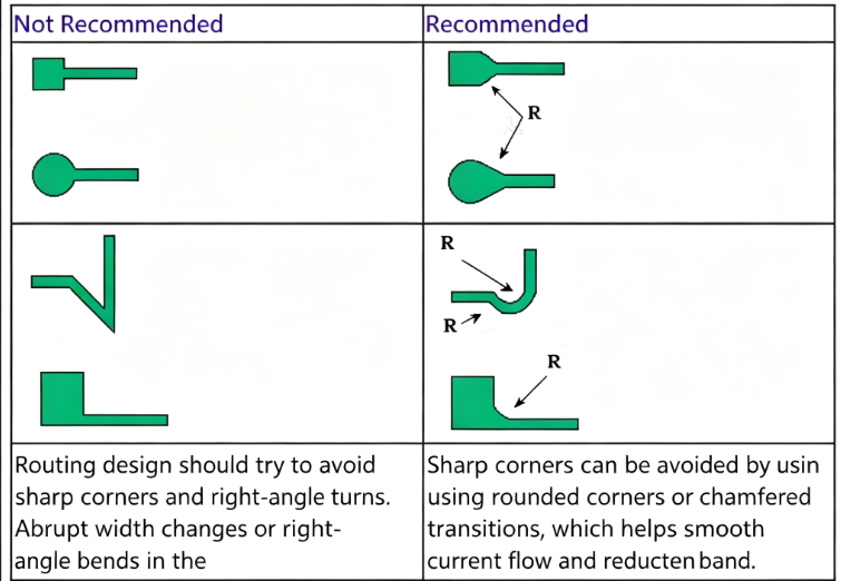
To improve the reliability and flexibility of the FPC, trace geometry should follow certain guidelines:
-
Avoid sharp corners – use rounded or 45‑degree corners to reduce stress concentration.
-
When traces change direction, use smooth arcs rather than abrupt bends, especially in areas that will be flexed repeatedly.
-
Keep traces as short and direct as possible to minimise signal loss and impedance variations.
-
For high‑flex applications, consider using a hatched (gridded) copper pattern instead of solid copper to improve flexibility.
These design practices help prevent cracking of copper traces during bending and ensure consistent electrical performance over the product's lifetime.
About Maxipcb
Maxipcb empowers innovators to turn cutting-edge technologies into reality.We offer one-stop solutions for design, simulation, testing, PCB manufacturing, component procurement and SMT assembly, enabling efficient development, rapid deployment and risk control across the full product lifecycle.
Serving the world in communications, industrial automation, aerospace, automotive, semiconductor and beyond, we build a safer, more connected future together.
