Electromagnetic Interference (EMI) in circuit design has long been a troublesome issue, especially in the automotive field. To minimize EMI as much as possible, designers usually reduce the noise source by minimizing the loop area of high di/dt currents and lowering the switching slew rate during schematic design and PCB layout.
Electromagnetic Interference (EMI) in circuit design has long been a troublesome issue, especially in the automotive field. To minimize EMI as much as possible, designers usually reduce the noise source by minimizing the loop area of high di/dt currents and lowering the switching slew rate during schematic design and PCB layout.
However, even with meticulous layout and schematic design, it is sometimes still impossible to reduce conducted EMI to the required level. This is because noise depends not only on circuit parasitic parameters but also on current magnitude. In addition, the switching action of power devices generates discontinuous currents, which induce voltage ripples on the input capacitors and further increase EMI.
Therefore, additional methods are necessary to improve conducted EMI performance. This article mainly discusses the adoption of input filters to suppress noise and the addition of shielding cans to contain noise.
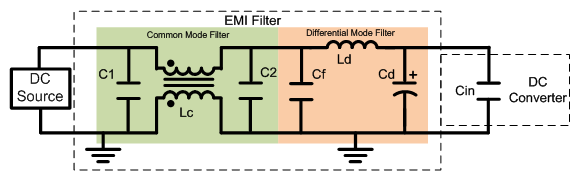
Figure 1: Schematic Diagram of EMI Filter
Figure 1 shows a simplified EMI filter consisting of a Common Mode (CM) filter and a Differential Mode (DM) filter. Typically, the DM filter is mainly used to suppress noise below 30MHz (DM noise), while the CM filter is primarily used to suppress noise from 30MHz to 100MHz (CM noise). In fact, both filters provide a certain attenuation effect on EMI noise across the entire frequency band.
Figure 2 shows the noise on the input leads without a filter, including positive and negative noise, with the peak and average levels of the noise marked. The test system uses the LMR14050SSQDDARQ1 chip to output 5V/5A, which supplies power to the subsequent TPS65263QRHBRQ1 chip, and the latter outputs 1.5V/3A, 3.3V/2A, and 1.8V/2A simultaneously. Both chips operate at a switching frequency of 2.2MHz. The conducted EMI standard shown in the figure is CISPR25 Class 5 (C5). For more information about this system, please refer to Application Note SNVA810.
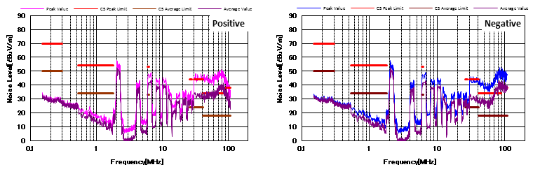
Figure 2: Noise Characteristics Under C5 Standard (Without Filter)]
Figure 3 shows the EMI results after adding a DM filter. It can be seen that the DM filter attenuates the mid-band DM noise (2MHz to 30MHz) by nearly 35dBμV/m. In addition, the high-frequency noise (30MHz to 100MHz) is also reduced but still exceeds the limit level. This is mainly because the DM filter has limited ability to suppress high-frequency CM noise.
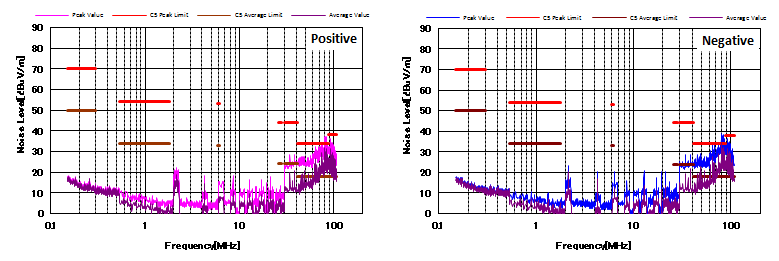
Figure 3: Noise Characteristics Under C5 Standard (With DM Filter)
Figure 4 shows the noise characteristics after adding both CM and DM filters. Compared with Figure 3, the addition of the CM filter reduces the CM noise by nearly 20dBμV/m, and the EMI performance meets the CISPR25 C5 standard.
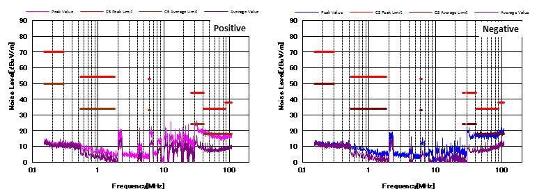
Figure 4: Noise Characteristics Under C5 Standard (With CM and DM Filters)
Figure 5 shows the noise characteristics with CM and DM filters under a different layout (the filters are the same as those in Figure 4). Compared with Figure 4, the noise across the entire frequency band increases by approximately 10dBμV/m, and the high-frequency noise even exceeds the average limit of the CISPR25 C5 standard.
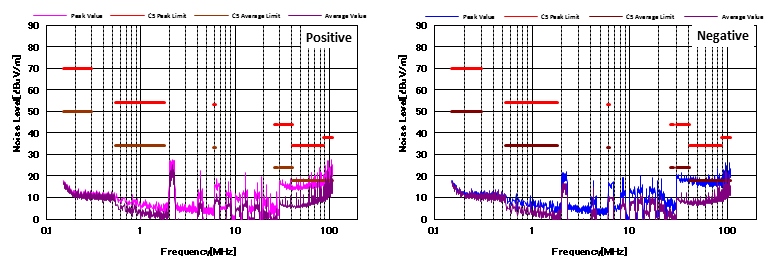
Figure 5: Noise Characteristics Under C5 Standard (With CM and DM Filters, Different Layout)]
The difference in noise results between Figure 4 and Figure 5 is mainly caused by PCB routing differences, as shown in Figure 6. In the routing of Figure 5 (right side of Figure 6), a large area of copper pour (GND) surrounds the DM filter and forms parasitic capacitances with the Vin trace. These parasitic capacitances provide an effective low-impedance path for high-frequency signals to bypass the filter. Therefore, to maximize the filter performance, all copper pour around the filter must be removed, as shown in the routing on the left side of Figure 6.
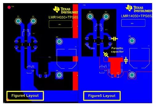
Figure 6: Different PCB Routing Designs
In addition to adding filters, another effective method to optimize EMI performance is to add a shielding can. A grounded metal shielding can block noise from radiating outward. Figure 7 recommends a shielding can placement method, where the shielding can completely covers all components on the board.
Figure 8 shows the EMI results after adding both filters and a shielding can. As shown, the noise across the entire frequency band is almost completely eliminated by the shielding can, resulting in excellent EMI performance. This is mainly because the long input leads, which act as antennas, couple a large amount of radiated noise, and the shielding can effectively isolate them. In this design, mid-band noise is also coupled to the input leads in this way.
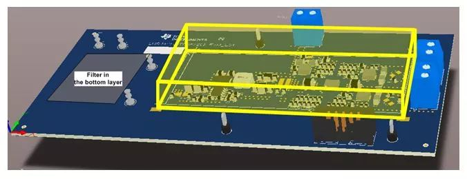
Figure 7: 3D Model of PCB with Shielding Can
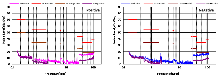
Figure 8: Noise Characteristics Under C5 Standard (With CM, DM Filters and Shielding Can)]
Figure 9 also shows the noise characteristics with filters and a shielding can. Unlike Figure 8, the shielding can in Figure 9 is a metal enclosure that wraps the entire circuit board, with only the input leads exposed. Even with this shielding can, some radiated noise can still bypass the EMI filter and couple to the power traces on the PCB, resulting in worse noise characteristics than Figure 8. Interestingly, the high-band noise characteristics in Figure 4, Figure 8, and Figure 9 (with the same layout and routing) are almost identical. This is because after adding the EMI filter, almost no high-frequency radiated noise can be coupled to the input leads.
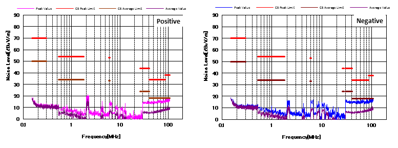
Figure 9: Noise Characteristics Under C5 Standard (With CM, DM Filters and Metal Shielding Enclosure)]
In summary, adding EMI filters or shielding cans can effectively improve EMI performance. At the same time, the PCB routing of the filters and the placement of the shielding cans must be carefully considered.
About Maxipcb
Maxipcb empowers innovators to turn cutting-edge technologies into reality.
We offer one-stop solutions for design, simulation, testing, PCB manufacturing, component procurement and SMT assembly, enabling efficient development, rapid deployment and risk control across the full product lifecycle.Serving the world in communications, industrial automation, aerospace, automotive, semiconductor and beyond, we build a safer, more connected future together.
