Multilayer PCB design requires a method to establish connections between layers, which is accomplished through the use of vias ranging from through-hole vias to via-in-pad technologies. Traces serve as horizontal connection elements, while vias act as vertical connection elements, enabling signals and power to be transmitted between board layers.
Multilayer PCB design requires a method to establish connections between layers, which is accomplished through the use of vias ranging from through-hole vias to via-in-pad technologies. Traces serve as horizontal connection elements, while vias act as vertical connection elements, enabling signals and power to be transmitted between board layers.
Before discussing via-in-pad, let's first introduce the different types of vias in PCB design.
I. Different Types of Vias in PCB Design
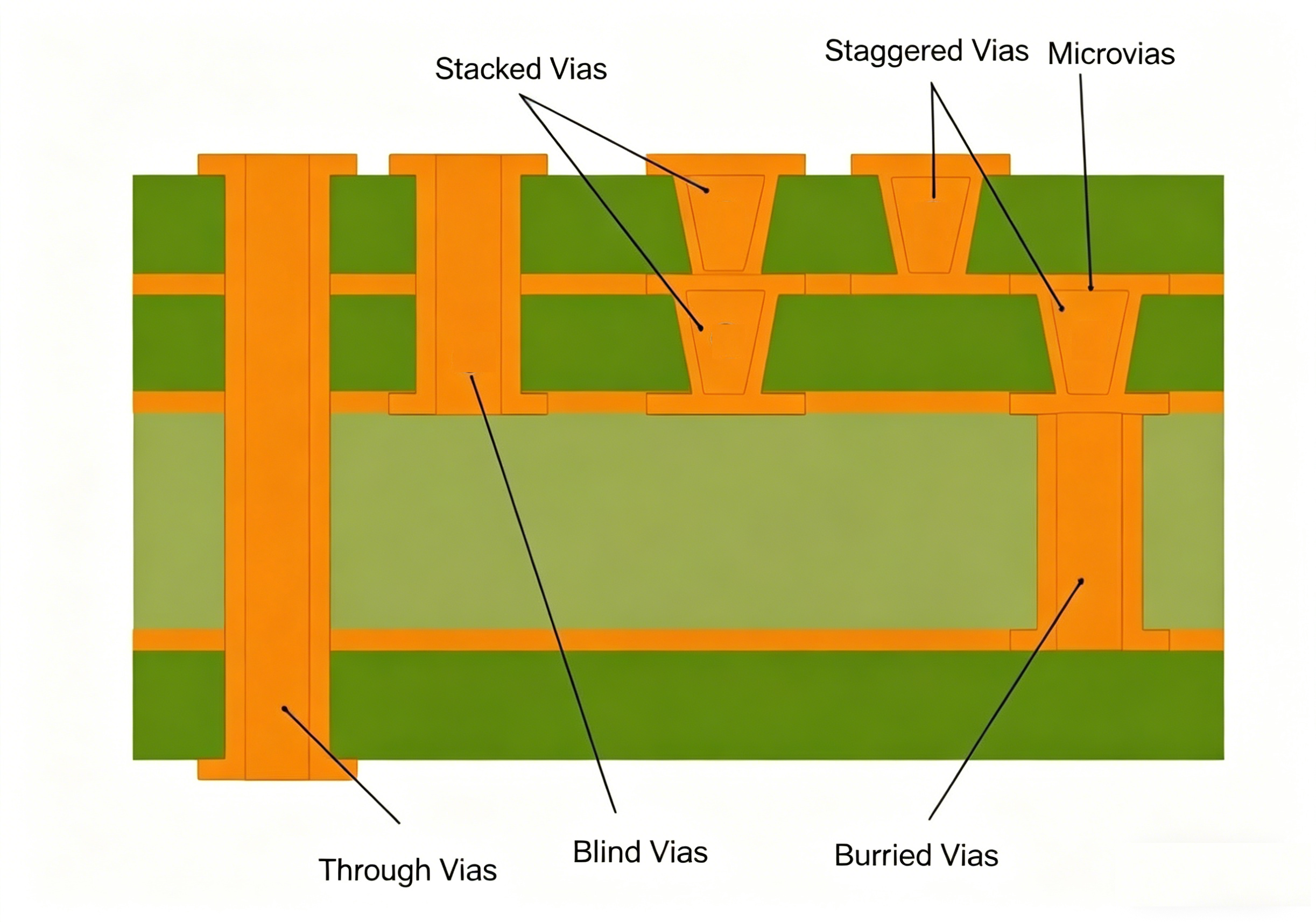
Stacked Vias Staggered Vias Micro Vias
Through Hole Blind Via Buried Via
1. Blind Via
Blind vias connect the outer layers to the internal layers of the PCB without passing through the entire board.
2. Buried Via
Buried vias connect only the internal layers of the PCB. They are more complex and costly to create, originate and terminate within the inner layers of the PCB, and are not visible from the outside.
3. Micro Via
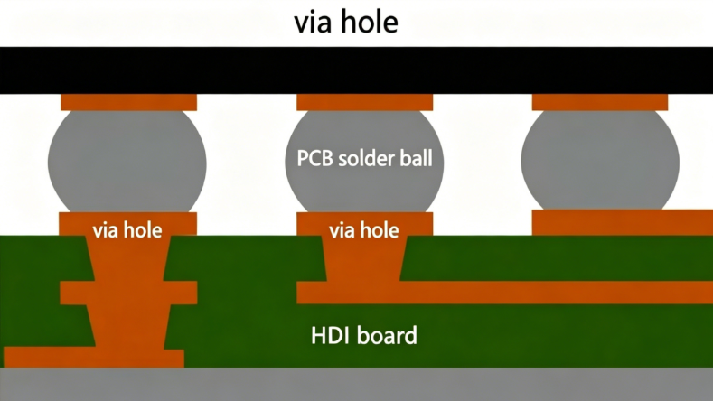
Micro vias are tiny holes with a size equal to or less than 6 mils, drilled using lasers on PCBs. Micro vias are typically implemented in HDI PCBs.
II. What is Via-in-Pad Technology?
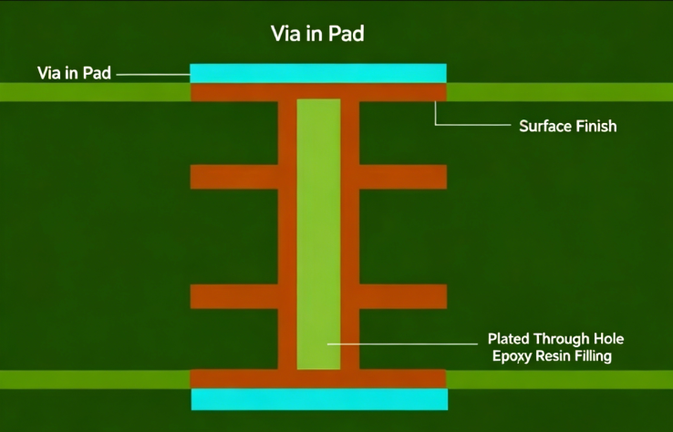
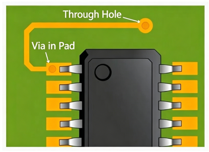
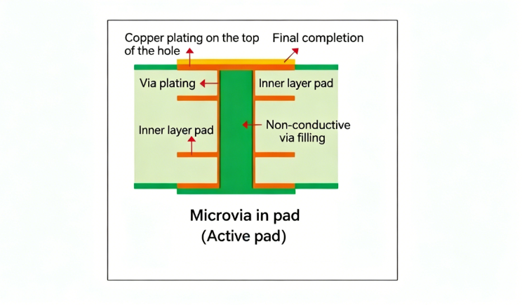
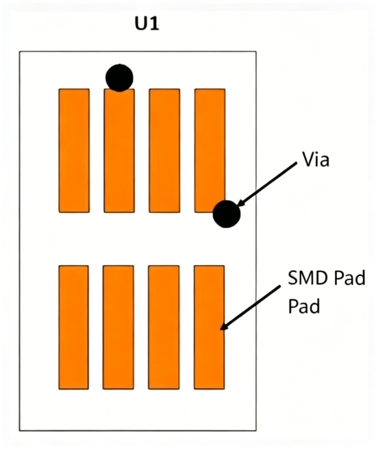
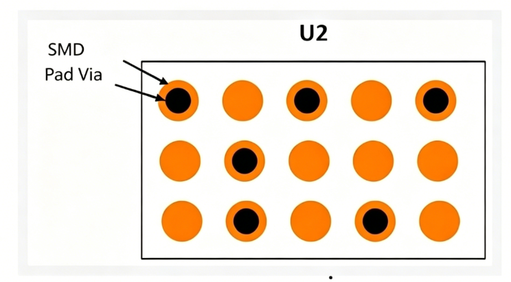
Via-in-pad refers to drilling a via directly on a pad, which is an SMD pad, usually referring to SMD pads of 0603 and above and BGA pads, commonly abbreviated as VIP (Via In Pad). Pads for through-hole components cannot be called via-in-pad, as through-hole pads require component insertion and soldering, so all through-hole pin pads have holes. The figure below shows a schematic diagram of via-in-pad.
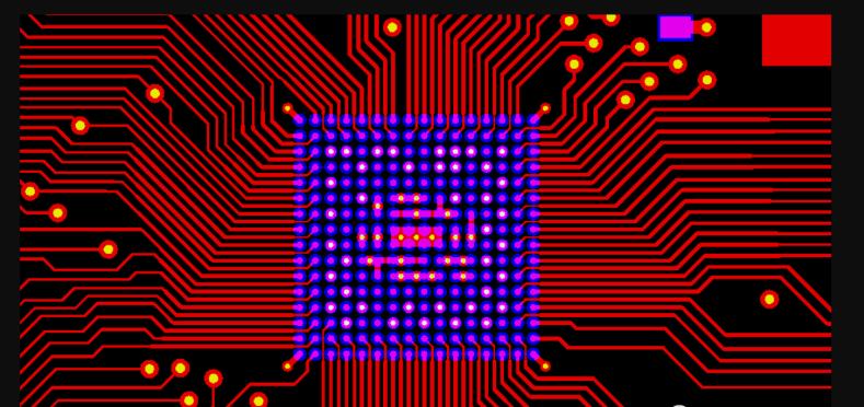
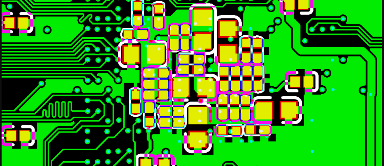
When the BGA pin pitch is too small for fan-out, the only solution is to use via-in-pad. Another scenario is when placing filter capacitors on the back of a BGA. When the BGA has a large number of pins, the filter capacitors on the back cannot avoid the vias from the pin fan-out, so vias have to be drilled on the filter capacitor pads.
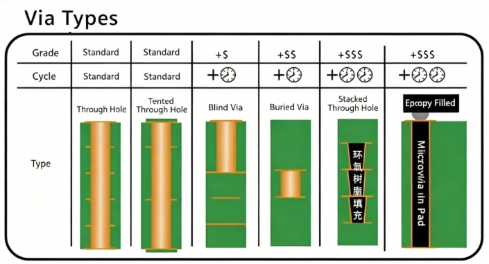
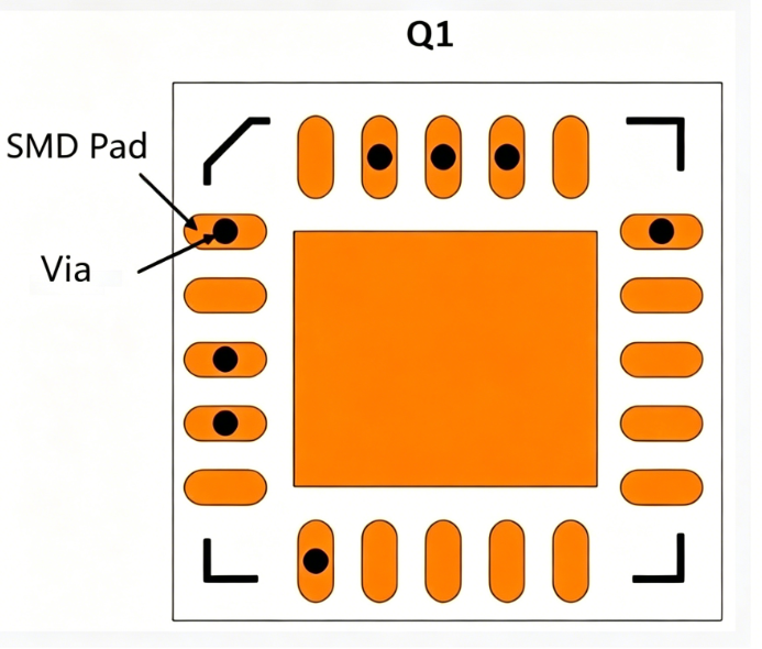
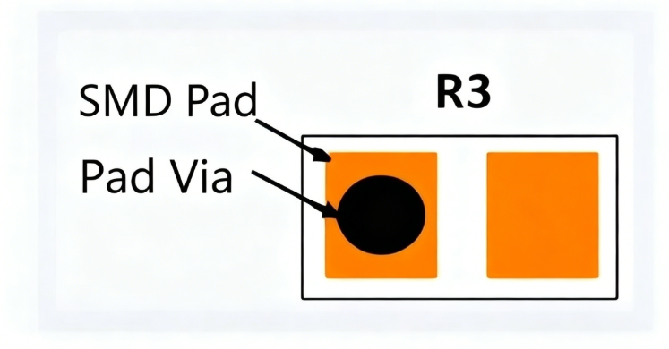
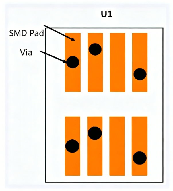
Therefore, there are two scenarios for via-in-pad: one on BGA pads and the other on SMD component pads. The following figures show various types of through holes and via-in-pad in PCB design, which are simple and clear.
Unlike traditional vias where signal-carrying traces are routed away from the pad to the via, via-in-pad enables miniaturization of PCB form factors by reducing the space occupied by trace routing. The most typical application of these in-pad holes is for BGA components with a pitch of 0.5 mm or less.
Via-in-pad technology minimizes signal path length, thereby reducing parasitic inductance and capacitance effects.
III. Via-in-Pad Design
Here we will discuss when via-in-pad design is required and when it is not.
1. No Need for Via-in-Pad Design
Before PCB routing, fan-out work is required to facilitate inner layer routing. For fan-out of BGA devices with a large number of pins, vias must be fanned out at the center position between the pads in the BGA area. Regarding the setting parameters for BGA fan-out: via diameter 0.15-0.2mm, line width 3-4mil, annular ring 0.3-0.4mm. Therefore, the BGA pin pitch needs to be greater than 0.35mm for normal fan-out.
2. Requirement for Via-in-Pad Design
Before BGA fan-out, we need to set the via hole diameter. Otherwise, an inappropriate hole diameter will prevent effective fan-out or result in abnormal fan-out. When the BGA pin pitch is too small for fan-out, via-in-pad design is required, with routing from the inner layer or the bottom layer of the BGA device.
1) Via-in-Pad on BGA
Devices with fewer package pins generally do not require via-in-pad design. For BGA devices with many pins, the fan-out vias occupy routing space. If vias are designed as via-in-pad, drilled directly on the BGA pads, routing space can be reserved. When the pin pitch is too small for routing, via-in-pad is designed for routing from other layers.
2) Via-in-Pad on Filter Capacitors
When a large number of vias are required for routing within a BGA device, it is difficult to place filter capacitors on the back of the BGA without avoiding the vias. Therefore, vias are drilled on the pads, becoming via-in-pad.
IV. Via-in-Pad Manufacturing Process
- Vias on BGA are generally defined as via-in-pad, which require resin plugging. Electroplating capping is performed on the resin to facilitate customer soldering, unless the customer specifically requires no plugging for holes on BGA.
- In addition to BGA, when the customer requires resin plugging for all vias, vias on SMD pads are also defined as via-in-pad.
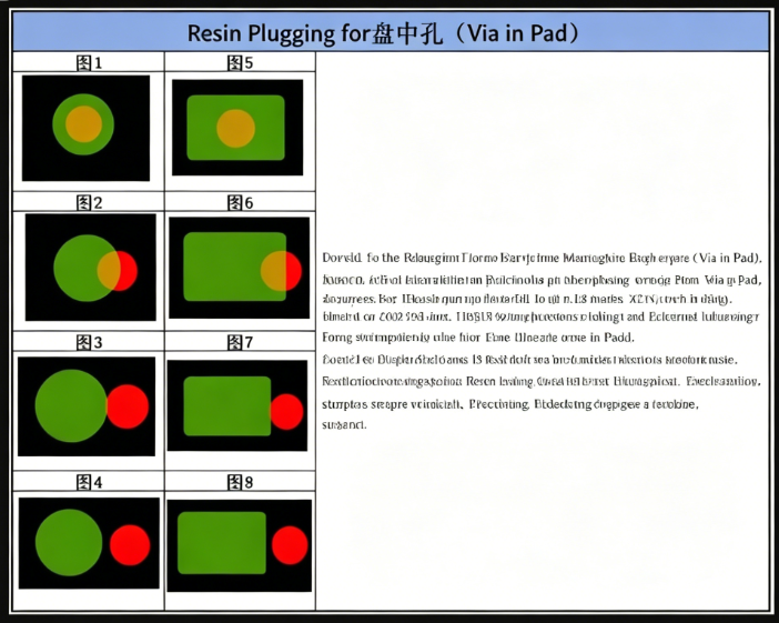
The following are examples of via-in-pad:
- Figures 1 and 5 show standard via-in-pad.
- Figures 2 and 6 also belong to via-in-pad.
- Figures 3 and 7 show cases where the via is tangent to the pad (also treated as via-in-pad).
- Figures 4 and 8 show cases where the via is isolated from the pad (no resin plugging required).
- Figures 1, 2, 3, 5, 6, 7 are treated with resin plugging, unless the customer has special requirements.
Via-in-Pad Manufacturing Process Flow
Drill via-in-pad → Plate via copper → Plug with resin → Cure → Grind → Copper reduction → Remove excess glue → Drill other non-via-in-pad holes (usually component holes and tool holes) → Plate via copper and VCP surface copper → Normal process...
The following are examples of with and without via-in-pad process:
-
Without via-in-pad process
Via-in-pad requires resin plugging and then copper plating on the plugged resin to facilitate soldering. If via-in-pad is not processed and no plugging is performed, the result is small soldering area, tin beads trapped in the holes or oil explosion, leading to cold solder joints.
-
With via-in-pad process
If BGA pads are small and via-in-pad is designed, there is basically no soldering area left. Therefore, via-in-pad requires resin plugging and electroplating to fill the holes to facilitate soldering and avoid poor soldering phenomena.
V. Advanced Via-in-Pad Design
You can use the solder mask as a blocking medium to prevent solder from being drawn into the via cavity, which is a traditional method. For VIP structures, a completely filled via cavity is required to eliminate trapped air and outgassing, and a precisely flat surface is needed for reliable connection of fine-pitch BGAs.
Manufacturing options available for VIP include mechanical drilling, electroplating and non-conductive epoxy filling methods, as well as laser ablation and all-copper filled via-in-pad methods.
1. Non-Conductive Epoxy Via Filling
As mentioned above, mechanically drilled vias in pads need to be filled with epoxy resin. The choice of epoxy resin largely depends on the coefficient of thermal expansion (CTE) of the via-in-pad filling material and the laminate used. This is important because when the PCB undergoes heating and cooling stages during the lamination process, the filling material will move with or against the surrounding laminate material, which can lead to stress-induced fractures or even circuit breaks.
Since the CTE of non-conductive epoxy is closer to that of the laminate, it is a common and cost-effective option. The PCB design and stack-up will ultimately determine the type of epoxy resin required to fill the vias.
2. Via-in-Pad Generation
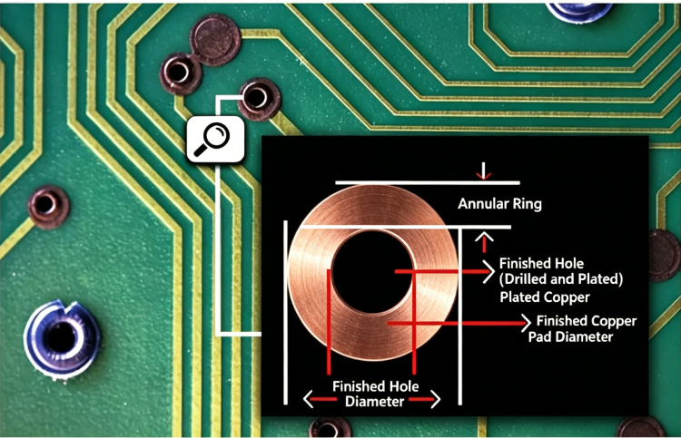
A key characteristic of the component/device footprint that determines the manufacturing method used to create via-in-pad is the pad diameter. To meet the minimum annular ring requirements for IPC Class 2 or 3, the pad size should be sufficient to accommodate the via diameter plus the material dimensions required for manufacturing tolerances.
When using standard mechanical drilling, the pilot drill size (pre-plating drill diameter) and annular ring need to be considered. The annular ring is the pad remaining after drilling and copper plating. When the remaining annular ring is insufficient after specifying the minimum drill diameter, laser micro vias need to be used. It is important to clarify that the annular ring is the copper pad area around the drilled and finished hole.
3. Common Via-in-Pad Designs
-
BGA pads with via-in-pad
-
QFN device pads with via-in-pad
-
Vias on component pads such as resistors or capacitors
-
Vias located within IC pads, connectors or multi-pin components
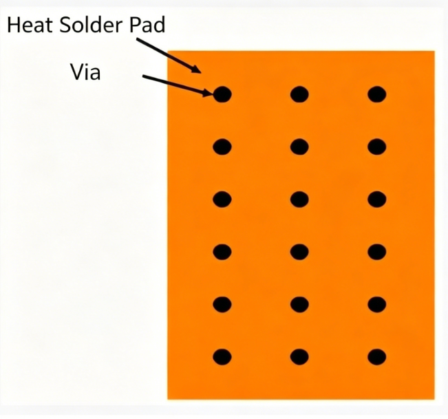
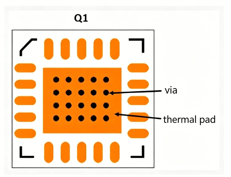
In some cases, via filling is not required. For example, thermal pads do not require soldering, so they are not considered via-in-pad.
4. Via-in-Pad Not Requiring Solder Filling
-
Thermal pads not requiring solder filling
-
Vias not on pads
When vias are not actually placed on pads, via filling is also not required.
VI. Advantages of Via-in-Pad Routing
VIP routing is used when board size is limited, design components occupy very small space, and surface routing options are restricted by design constraints. Via-in-pad routing is commonly used with BGAs.
It is also worth noting that when PCBs have complex devices in compact areas, designers place vias in surface mount device (SMD) pads to fan out connections.
When using VIP routing, PCBs also have other advantages compared to other routing options:
- Easier routing for fine-pitch Ball Grid Arrays (BGAs), which can be as small as 32 and 40 mils (0.8 mm and 1 mm).
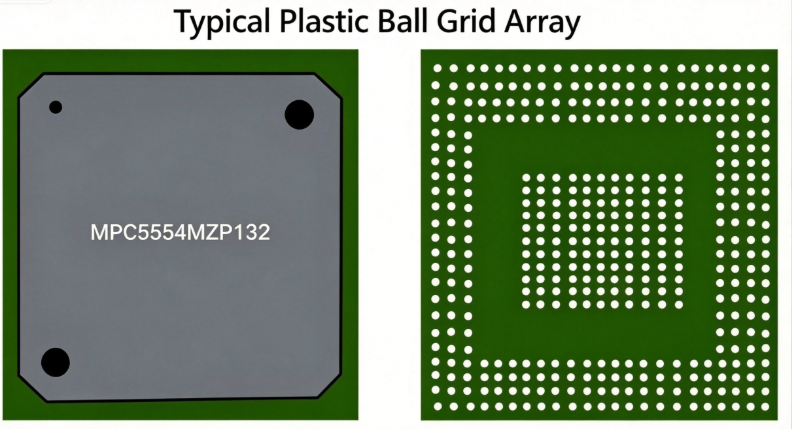
- When surface routing is eliminated, bypass capacitors can be placed closer to the component, minimizing inductance, which is useful for enhancing thermal management.
- Since vias are directly under the component, there is no need for via tenting. Via tenting involves sealing open vias that may draw in solder paste during assembly.
- Via-in-pad routing is useful for grounding high-frequency components.
VII. Disadvantages of Via-in-Pad Routing
Via-in-pad routing can be implemented by overcoming certain complexities in manufacturing. However, for manufacturers, eliminating surface protrusions requires more complex steps as follows:
- Via-in-pad routing requires the creation and filling of additional vias, adding new steps including drilling additional holes, electroplating the vias with conductive material (such as copper), then filling the vias with epoxy resin and capping them with copper.
- Capped vias are sometimes prone to outgassing. Outgassing or degassing refers to the release of vapor due to thermal expansion of gases, which is the result of phase change from liquid to vapor during heating in the lamination process.
- Outgassing leads to the formation of voids in solder joints as bubbles move upward through the vias.
VIII. Via-in-Pad Routing Tips
If your PCB design requires the creation of via-in-pad, you need to reduce manufacturing problems and minimize the additional cost and time required for this specific type of routing. You can use the following via-in-pad guidelines for surface mount device routing:
- Refer to the manufacturer's recommendations for component placement as well as capping and filling.
- Place micro vias on one layer of the PCB.
- Ensure that the non-component side is covered with solder mask.
- Avoid leaving vias open unless necessary - leaving vias open exposes the via copper to the environment, leading to oxidation or degradation, which shortens PCB life.
About Maxipcb
Maxipcb empowers innovators to turn cutting-edge technologies into reality.
We offer one-stop solutions for design, simulation, testing, PCB manufacturing, component procurement and SMT assembly, enabling efficient development, rapid deployment and risk control across the full product lifecycle.Serving the world in communications, industrial automation, aerospace, automotive, semiconductor and beyond, we build a safer, more connected future together.