Baseband signals cannot leave wires and are difficult to propagate across space. The responsibility of an RF system is to embed raw information into carriers with sufficiently high frequencies (usually ranging from hundreds of kilohertz to hundreds of gigahertz), so that electromagnetic waves can break free from the constraints of wires and complete long-distance energy and information exchange. To achieve this goal, six types of functions must be implemented at the hardware level:
Core Problems to Be Solved in Radio Frequency (RF) Design
Baseband signals cannot leave wires and are difficult to propagate across space. The responsibility of an RF system is to embed raw information into carriers with sufficiently high frequencies (usually ranging from hundreds of kilohertz to hundreds of gigahertz), so that electromagnetic waves can break free from the constraints of wires and complete long-distance energy and information exchange. To achieve this goal, six types of functions must be implemented at the hardware level:
1. Carrier Generation and Information Embedding
- Functional Units: Voltage-Controlled Oscillator (VCO), Phase-Locked Loop (PLL), I/Q Modulator, etc.
- Design Objectives: Programmable output frequency points, low phase noise, and small modulation errors, ensuring that information can be "cleanly" modulated to the specified frequency band.
2. Power Amplification
- Functional Units: Low-Noise Amplifier (LNA), Power Amplifier (PA).
- Design Objectives: Amplify microvolt-level signals to detectable levels without introducing significant noise in the receiving link; boost milliwatt-level signals to watt-level in the transmitting link to overcome path loss.
3. Frequency Domain Filtering
- Functional Units: Various filters (LC, SAW, BAW, microstrip), diplexers, switched filter banks.
- Design Objectives: Allow only the target channel to pass, suppress adjacent channels, images, harmonics and other unwanted components, and reduce the system interference budget.
4. Power Transmission and Interface Matching
- Functional Units: Microstrip lines, striplines, coaxial cables, baluns, matching networks.
- Design Objectives: Deliver amplified power to the antenna port efficiently and with low reflection; meanwhile, transfer the power received by the antenna to the receiving front-end without loss.
5. Frequency Conversion
- Functional Units: Mixers, local oscillator (LO) links.
- Design Objectives: Shift the RF spectrum to an intermediate frequency or directly to zero IF for subsequent digital processing; or reversely shift the baseband signal back to RF for transmission.
6. Conversion Between Electromagnetic Waves and Guided Waves
- Functional Units: Antennas and their feed structures.
- Design Objectives: Convert guided waves to spatial waves, or spatial waves to guided waves, taking into account radiation pattern, efficiency, bandwidth and size.
Essential Characteristics of RF Systems
In summary, an RF system manipulates electromagnetic waves to achieve efficient, low-loss, and low-disturbance information transmission under the condition that the wavelength is comparable to the circuit size. Each transmission is accompanied by the redistribution of energy, spectrum and time.
Major Factors Destroying Signal Integrity
Linear Distortion
- Insufficient Amplitude Flatness: Gain differences at different frequencies lead to waveform envelope distortion.
- Group Delay Variation: Inconsistent phase slope causes inter-symbol interference in wideband digital signals.
Nonlinear Distortion
- Harmonics and Spurs: Integer or fractional frequency components generated by amplifiers and mixers.
- Intermodulation Products: New frequency components generated in multi-carrier scenarios, falling into the receiving band.
- Gain Compression and Phase Deviation: Amplifier gain decreases under large signals, and modulation vectors deviate from ideal positions.
- Spectral Regrowth: Deterioration of Adjacent Channel Power Ratio (ACPR), interfering with adjacent channel users.
Noise
- Thermal Noise: Generated by resistors and transistor channels, determining the limit of receiving sensitivity.
- Flicker Noise: 1/f characteristic in low frequency bands, deteriorating near-carrier phase noise.
- Phase Noise: Random jitter of oscillators, reducing modulation accuracy and adjacent channel selectivity.
Interference and Coupling
- External Electromagnetic Interference: From co-channel or adjacent-channel transmitters, switching power supplies, etc.
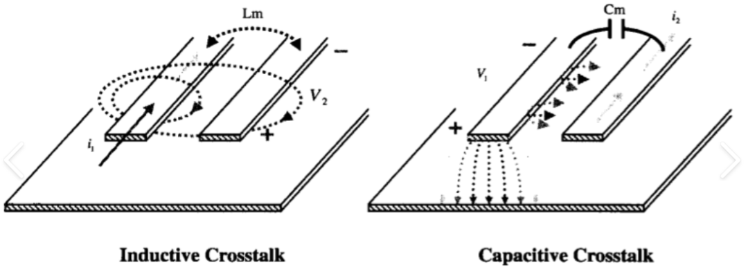
- Internal Crosstalk: Capacitive, inductive or radiative coupling caused by unreasonable layout and routing.
Core Contradictions in RF Design
Under high-frequency conditions, parasitic parameters, material non-idealities, layout coupling, and device nonlinearity will significantly alter circuit behavior. The task of RF engineers is to iterate repeatedly between theoretical models, simulation tools and measured results to find a trade-off solution that takes into account efficiency, linearity, noise, cost and size. The ultimate goal is: in a complex electromagnetic environment, the bit stream sent by the transmitter can still be restored by the receiver with a sufficiently low bit error rate after passing through the spatial channel and a series of non-ideal hardware.