This article elaborates on the considerations for layout design of mixed-signal PCBs, covering component placement, board layer stacking, and ground plane management. The guidelines discussed provide a practical approach to mixed-signal board layout design and shall benefit engineers of all backgrounds.
This article elaborates on the considerations for layout design of mixed-signal PCBs, covering component placement, board layer stacking, and ground plane management. The guidelines discussed provide a practical approach to mixed-signal board layout design and shall benefit engineers of all backgrounds.
Introduction
Mixed-signal PCB design requires fundamental understanding of analog and digital circuits to minimize (if not prevent) signal interference. Components in modern systems operate in either the digital or analog domain and must be carefully designed to ensure signal integrity of the entire system.
As a critical part of the mixed-signal development process, PCB layout can be daunting, and component placement is only the starting point. Other factors must be considered, including board layers and proper layer management to minimize interference caused by parasitic capacitance (unintended capacitance between PCB planes).
Grounding is also a critical step in mixed-signal system PCB layout design. Although grounding is a frequently debated topic in the industry, establishing a standardized methodology is not always straightforward for engineers. For instance, a single issue with high-quality grounding can affect the entire layout of a high-performance mixed-signal PCB design; thus, this aspect shall not be overlooked.
Component Placement
Similar to building a house, a system floor plan must be created before placing circuit components. This step lays the foundation for overall design integrity and helps avoid interference from high-noise signals.
When developing the floor plan, it is recommended to follow the signal path of the schematic, especially for high-speed circuits. Component placement is also a key design aspect. Designers shall identify critical functional modules, signals, and interconnections between modules to determine optimal component locations. For example, connectors are best placed at board edges, while auxiliary components (e.g., decoupling capacitors and crystal oscillators) must be placed as close as possible to mixed-signal devices.
Separation of Analog and Digital Modules
To minimize common return paths for analog and digital signals, separate analog and digital modules to prevent mixing of analog and digital signals.
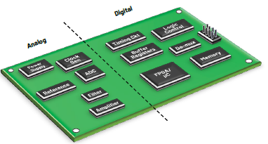
Figure 1. Separation of Analog and Digital Circuits
Figure 1 shows a good example of analog and digital circuit separation. The following considerations apply when partitioning analog and digital sections:
- Sensitive analog components (e.g., amplifiers and voltage references) are recommended to be placed within the analog plane. Similarly, high-noise digital components (e.g., logic control and timing modules) must be placed on the opposite/digital plane.
- If the system includes a mixed-signal analog-to-digital converter (ADC) or digital-to-analog converter (DAC) with low digital current, it can be treated similarly to analog components contained in the analog plane.
- For designs with multiple high-current ADCs and DACs, separate analog and digital power supplies are recommended. That is, AVCC shall be bonded to the analog section, while DVDD shall be connected to the digital section.
- Microprocessors and microcontrollers may occupy space and generate heat. These devices must be placed at the center of the board for better heat dissipation and close to their associated circuit modules.
Power Module
The power supply is a critical circuit component that shall be properly handled. As a rule of thumb, power modules must be isolated from the rest of the circuit while remaining close to the components they power.
Devices in complex systems may have multiple power pins; in such cases, dedicated power modules can be used for analog and digital sections respectively to avoid high-noise digital interference.
On the other hand, power traces shall be short and straight, with wide traces to reduce inductance and avoid current limiting.
Decoupling Techniques
Power Supply Rejection Ratio (PSRR) is one of the key parameters designers must consider to achieve target system performance. PSRR measures device sensitivity to power supply variations and ultimately determines device performance.
To maintain optimal PSRR, it is necessary to prevent high-frequency energy from entering the device. To this end, a combination of electrolytic and ceramic capacitors can be used to properly decouple device power supplies to a low-impedance ground plane.
The purpose of proper decoupling is to create a low-noise environment for circuit operation. The basic rule is to provide the shortest path for easy current return.
Designers must pay attention to high-frequency filtering recommendations for each device. More importantly, the following list serves as a guide providing general decoupling techniques and proper implementation methods:
- Electrolytic capacitors act as charge reservoirs for transient currents to minimize low-frequency noise on the power supply, while low-inductance ceramic capacitors are used to reduce high-frequency noise. Additionally, ferrite beads are optional but add high-frequency noise isolation and decoupling.
- Decoupling capacitors must be placed as close as possible to device power pins. These capacitors shall be connected to large areas of the low-impedance ground plane via vias or short traces to minimize additional series inductance.
- Smaller capacitors (typically 0.01μF to 0.1μF) shall be placed as close as possible to device power pins. This arrangement prevents unstable operation when multiple outputs of the device switch simultaneously. Electrolytic capacitors (typically 10μF to 100μF) shall be placed no more than 1 inch from device power pins.
- For easier implementation, vias near device GND pins can be used to connect decoupling capacitors to the ground plane via T-connections instead of creating traces. See Figure 2 for an example.
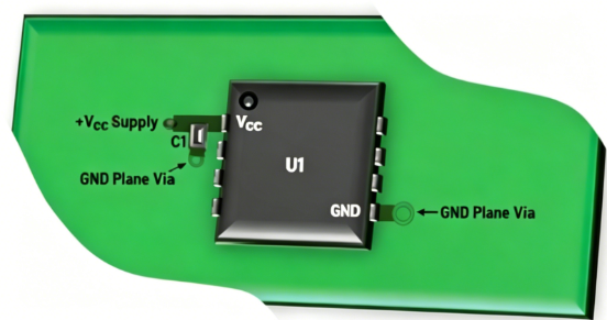
Figure 2. Decoupling Technique for Power Pins
Board Layer Stackup
Once component placement and floor planning are completed, we can examine another aspect of board design—commonly referred to as board layer stackup. It is strongly recommended to consider board layers before PCB routing, as this determines the allowable return paths for system design.
Board layer stackup refers to the vertical arrangement of copper layers in the board. These layers shall manage current and signals across the entire board.
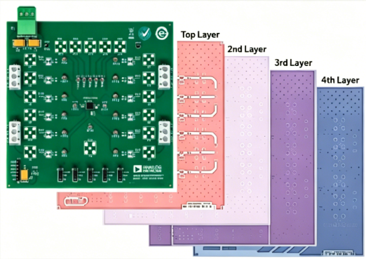
Figure 3. Example of a 4-Layer PCB
Figure 3 shows a visual representation of board layers. Table 1 details the setup of a typical 4-layer PCB:
Table 1. Typical 4-Layer PCB Stackup
| Layer Position |
Layer Type |
| 1 |
Digital/Analog Signal (Top Layer) |
| 2 |
Ground |
| 3 |
Power Plane |
| 4 |
Auxiliary Signal (Bottom Layer) |
Typically, high-performance data acquisition systems shall have four or more layers. The top layer is usually used for digital/analog signals, while the bottom layer is used for auxiliary signals. The second layer (ground layer) acts as a reference plane for impedance-controlled signals, reducing IR drop and shielding digital signals in the top layer. Finally, the power plane is located at the third layer.
Power and ground planes must be adjacent to each other, as they provide additional inter-plane capacitance that aids high-frequency decoupling of the power supply.
For ground planes, recommendations for mixed-signal design have changed over the years. Splitting the ground plane into analog and digital sections made sense for many years, but a new approach is recommended for modern mixed-signal devices. Proper floor planning and signal separation shall prevent issues related to high-noise signals.
Ground Plane: Split or Not Split?
Grounding is a critical step in mixed-signal PCB layout design. A typical 4-layer PCB shall have at least one layer dedicated to the ground plane to ensure return signals flow through low-impedance paths. All integrated circuit ground pins shall be routed and directly connected to the low-impedance ground plane to minimize series inductance and resistance.
For mixed-signal systems, separating analog and digital grounds has become a standard grounding practice. However, mixed-signal devices with low digital current are best managed with a single ground. Furthermore, designers must consider which grounding practice is most appropriate based on mixed-signal current requirements. Designers shall evaluate two grounding approaches.
Single Ground Plane
For mixed-signal systems with a single low-digital-current ADC or DAC, a solid single ground plane is the optimal approach. To understand the importance of a single ground layer, we need to review return currents. Return current refers to the current that returns to ground and flows between devices to form a complete loop. To prevent mixed-signal interference, every return path must be tracked throughout the PCB layout.
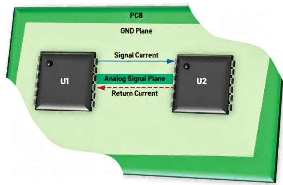
Figure 4. Return Current in a System with a Solid Ground Plane
The simple circuit in Figure 4 illustrates the advantages of a solid single ground plane over a split ground plane. Signal current has a return current of equal magnitude but opposite direction. This return current flows back to the source in the ground plane, taking the path of least impedance.
For low-frequency signals, return current flows along the path of least resistance, typically a straight line between device ground reference points. For higher-frequency signals, part of the return current attempts to follow the signal path, as impedance along this path is lower, minimizing the loop formed between outgoing and return currents.
Split Analog and Digital Grounds
For complex systems where a solid ground scheme is difficult to implement, split grounds may be more suitable. A split ground plane is another common method, dividing the ground plane into two sections: analog ground plane and digital ground plane. This applies to more complex systems with multiple mixed-signal devices drawing high digital current. Figure 5 shows an example of a system with a split ground plane.
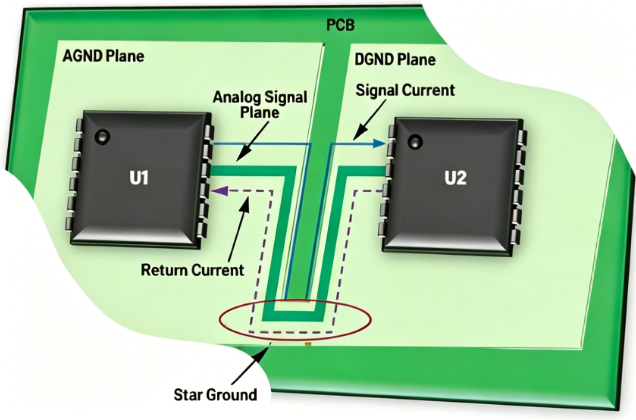
Figure 5. Return Current in a System with Split Ground Planes
For systems with split ground planes, the simplest solution for overall grounding is to eliminate discontinuities in the ground plane and allow return currents to take a more direct route back to the source via a star ground junction. Star ground is the junction where analog and digital ground planes are connected together in mixed-signal layout design.
In common systems, star ground can be associated with a simple narrow continuous junction between analog and digital ground planes. For more complex designs, star ground is often implemented with jumpers shunted to ground connectors. No current flows through the star ground, so connectors and jumper shunts capable of carrying high current are not required. The primary function of star ground is to ensure both grounds share the same reference level.
Designers must check grounding recommendations provided in each device’s datasheet to ensure compliance with grounding requirements and avoid grounding-related issues. On the other hand, mixed-signal devices with AGND and DGND pins can be connected to their respective ground planes, as star ground also connects both grounds at a single point. This way, all high-noise digital current flows through the digital power supply, to the digital ground plane, and back to the digital power supply, while being isolated from sensitive analog circuits. Isolation of AGND and DGND planes must be implemented on all layers of the multilayer PCB.
Other Common Grounding Practices
The following steps or checklist can be used to ensure proper grounding implementation in mixed-signal/digital systems:
- The star ground junction connection shall consist of wide copper traces.
- Inspect the ground plane for narrow traces; these connections are undesirable.
- Provide pads and vias to allow connection of analog and digital ground planes if necessary.
Conclusion
PCB layout for mixed-signal applications can be challenging. Creating a component floor plan is only the starting point. Proper management of board layers and development of an appropriate grounding scheme are also key points system designers must consider when striving for optimal performance in mixed-signal system layout. Developing a component floor plan helps lay the foundation for overall system design integrity. Proper organization of board layers aids in managing current and signals across the entire board. Finally, selecting the most favorable grounding scheme improves system performance and prevents issues related to high-noise signals and return currents.
About Maxipcb
Maxipcb empowers innovators to turn cutting-edge technologies into reality.
We offer one-stop solutions for design, simulation, testing, PCB manufacturing, component procurement and SMT assembly, enabling efficient development, rapid deployment and risk control across the full product lifecycle.Serving the world in communications, industrial automation, aerospace, automotive, semiconductor and beyond, we build a safer, more connected future together.
