Rigid-Flex Printed Circuit Board, abbreviated as Rigid-Flex, is a circuit structure that integrates both rigid substrates and flexible circuits on a single circuit board.
Rigid-Flex Printed Circuit Board, abbreviated as Rigid-Flex, is a circuit structure that integrates both rigid substrates and flexible circuits on a single circuit board.
Driven by the demands for miniaturization, low power consumption and high performance of electronic products, Rigid-Flex has become an important development direction of circuit substrate technology owing to its features of short dimension, small size, light weight and thin thickness.
With the increasingly powerful functions of modern electronic products, their internal structure and interconnection have become more complex, placing higher requirements on circuit boards. Traditional rigid PCBs or substrates can hardly meet the product requirements, so Rigid-Flex circuits have emerged naturally.
Rigid-Flex is composed of rigid substrates and flexible circuits, and the flexible circuits are directly connected to the rigid substrates without connectors.
Since the flexible part of Rigid-Flex can be bent flexibly, components mounted on Rigid-Flex can be arranged at various spatial angles, which is more flexible than the traditional electronic integration mode. It is like adding an extra dimension, thus being called "4D" integration. In electronic integration technology, the integration technology involving substrate bending and folding is defined as "4D" integration.
Rigid-Flex circuits feature small size, light weight and flexible bending performance, which can satisfy applications with complex spatial structures. They are widely used in modern electronic devices and have become an ideal choice for mobile communication products. To correctly design and apply Rigid-Flex circuits, we must first have a clear understanding of their basic characteristics. Through summary, the basic characteristics of Rigid-Flex circuits are attributed to three aspects: Multi-bending, Multi-stackup and Multi-zone.
01 Multi-bending
Multi-bending is the most intuitive impression of Rigid-Flex circuits, because the primary purpose of adopting flexible circuits is to realize bending. Rigid-Flex can be easily bent, folded and twisted.
Defined as Multi-bending, it means not just a few bends; complex Multi-bending can involve dozens of bends with a wide range of bending radii and angles. The small bending radius is barely larger than the substrate thickness, making the flexible circuit look folded in appearance. The bending angle of each segment can be flexibly designed from 0° to 180°.
Complex Rigid-Flex circuits contain dozens of bends, which are intertwined like a python, making it difficult to distinguish the top and bottom surfaces of the substrate. If we imagine walking on a Rigid-Flex circuit, the up, down, left and right directions keep changing, just like entering a "4D" space.
No matter how complex and variable the bends are, one principle must be observed: all parts of the circuit shall not interfere with each other in space. Therefore, the design of bends needs to take multiple factors into account, such as bending position, orientation, angle and radius. In addition, material thickness and material type are also important factors restricting bending.
In addition, vias and components are generally prohibited from being placed in bending areas, which are called Via keepout and Component keepout respectively.
02 Multi-stackup
Multi-stackup means that the number of layers and thickness vary in different areas of the substrate, that is, multiple layer stackup structures need to be defined for the substrate.
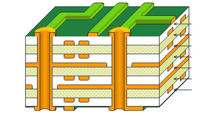
Any substrate has at least one stackup structure. For example, common 4-layer, 6-layer and 8-layer boards correspond to one stackup structure, which is called Single stackup, as shown in the figure below.
Single stackup
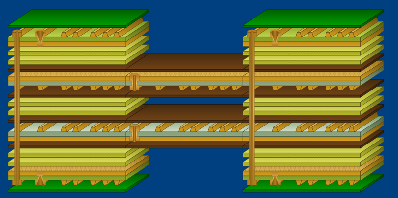
For Rigid-Flex substrates, multiple stackup structures (Multi-stackup) are often adopted, meaning the thickness and stackup structure differ at different positions of the substrate, as shown in the figure below. Thick stackups are usually applied to the rigid substrate parts, while the stackups of flexible circuit parts are relatively thin, suitable for bending and folding.
Multi-stackup
A Multi-stackup structure can include more than ten types. A new stackup needs to be defined as long as the stackup thickness is different or the materials in the stackup are different.
Among all these stackup structures, we can define new stackups or delete stackups, but there is one stackup that cannot be deleted and is always in the default position, which is called Primary stackup.
Primary stackup exists in both Multi-stackup and Single stackup. Single stackup has only Primary stackup, while Multi-stackup consists of Primary stackup plus other stackups.
03 Multi-zone
We have described Multi-stackup above, which refers to the adoption of different stackup structures in different areas of the substrate with different layer counts and thicknesses. Then, how are different stackups reflected in specific areas? This leads to the concept of Multi-zone.
For the entire Rigid-Flex circuit, it is divided into different zones according to functional requirements, and each zone is assigned a different or the same stackup structure, so that different stackups are allocated to specific areas.
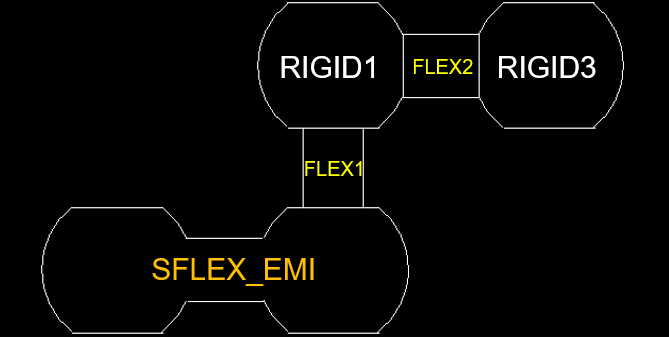
Multi-zonedefinition
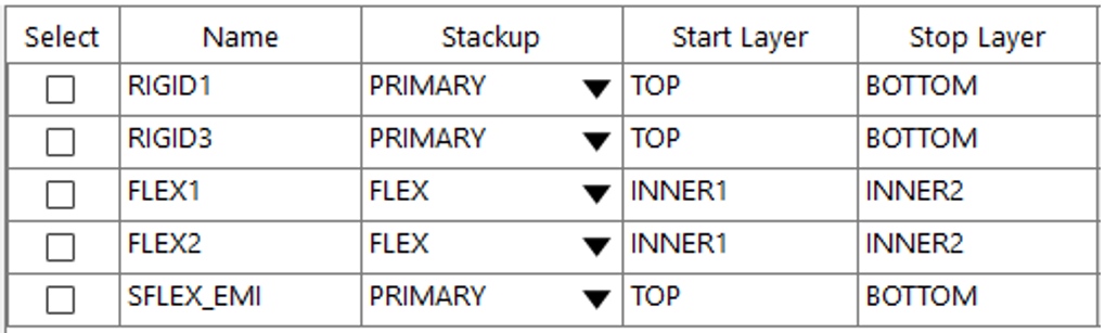
Assign stackup to each zone
The zone division of Rigid-Flex requires drawing zone shapes on the substrate and then specifying the stackup. Then, how is the stackup defined for the areas where no zone shape is drawn on the substrate? The default Primary stackup is applied.
Therefore, we know that not all areas of a Rigid-Flex circuit need to be defined as zones. The areas without zone definition adopt the default Primary stackup.
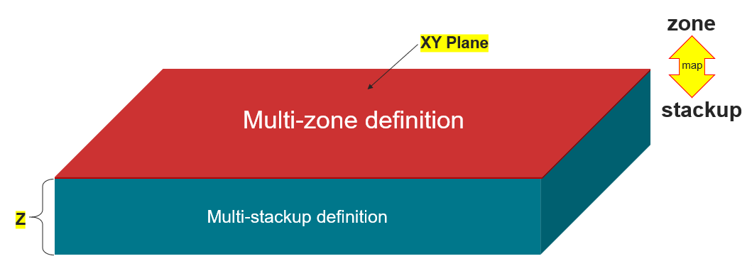
Physically, Multi-stackup is defined along the Z-axis of the substrate, and Multi-zone is defined on the XY plane of the substrate. They are relatively independent but interdependent.
Generally, we first define Multi-stackup, then define Multi-zone, and then map zones and stackups to each other. Multi-stackup and Multi-zone are interdependent. Although they can exist independently in design tools, one will lose its original function without the other.
Summary
Multi-bending, Multi-stackup and Multi-zone are the three most basic characteristics of Rigid-Flex PCBs.
With the rapid development of artificial intelligence (AI) technology, robots will surely enter every household and become a new growth point of human society. Since robots need to move like humans and each joint needs to be driven by circuits, Rigid-Flex circuits will be indispensable, and their market demand will surely usher in explosive growth.
About Maxipcb
Maxipcb empowers innovators to turn cutting-edge technologies into reality.
We offer one-stop solutions for design, simulation, testing, PCB manufacturing, component procurement and SMT assembly, enabling efficient development, rapid deployment and risk control across the full product lifecycle.Serving the world in communications, industrial automation, aerospace, automotive, semiconductor and beyond, we build a safer, more connected future together.