It is believed that when doing PCB design, everyone will find that the routing link is indispensable. The rationality of routing determines the aesthetics of the PCB and its production cost, and also reflects the quality of circuit performance and heat dissipation performance, as well as whether the performance of the device can be optimized.
It is believed that when doing PCB design, everyone will find that the routing link is indispensable. The rationality of routing determines the aesthetics of the PCB and its production cost, and also reflects the quality of circuit performance and heat dissipation performance, as well as whether the performance of the device can be optimized.
In the previous article, the editor mainly shared some design rules for PCB trace width and spacing. In this article, we will make a comprehensive summary of PCB routing methods for everyone, hoping to help you develop good design habits.
- The trace length shall include the length of vias and package pads.
- For routing angle, the 135° angle trace exit method is preferred. Routing at any angle will cause process problems in board fabrication.
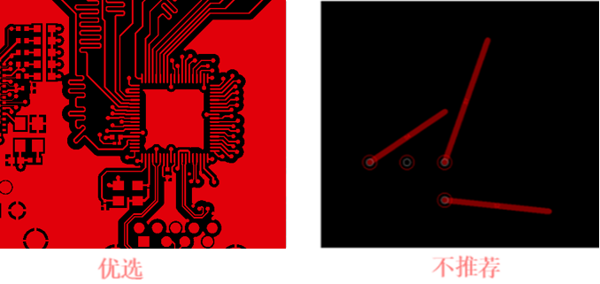
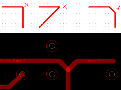
- Avoid right-angle or acute-angle routing, which will lead to trace width variation at the corner, impedance change and signal reflection, as shown in the figure below.
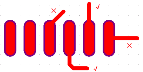
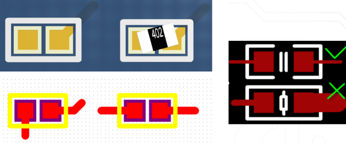
- Routing shall exit from the long direction of the pad, avoiding exit from the wide direction or the four corners of the pad. The distance between the routing corner and the pad should be more than 6mil, as shown in the figure below.
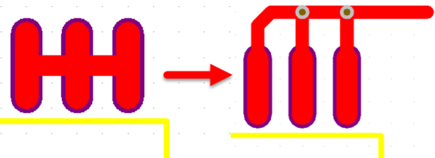
- As shown in the figure below, adjacent pads of the same net shall not be directly connected. They need to be connected after exiting the pad first; direct connection is likely to cause solder bridging during manual soldering.
- For small CHIP components, attention shall be paid to the symmetry of routing, keeping the routing width consistent at both ends. If copper is poured on one pin, copper pouring shall also be performed on the other pin as much as possible, to reduce component drift and rotation after SMT mounting, as shown in the figure below.
- For signals with ground wrapping requirements, the integrity of the ground wrapping must be ensured. GND vias shall be placed on the ground wrapping trace as much as possible, and the spacing between two GND vias shall not be too far, preferably kept at about 50-150mil, as shown in the figure below.
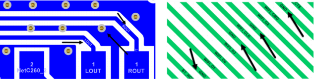
- Traces shall have a complete and continuous reference layer plane, avoiding high-speed signal crossing split planes. It is recommended that the high-speed signal be at least 40mil away from the edge of the reference plane, as shown in the figure below.

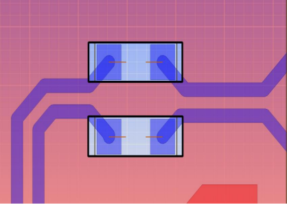
- Since the pads of surface mount devices will lead to impedance reduction, to minimize the impact of impedance discontinuity, it is recommended to hollow out a layer of the reference layer directly below the SMD pad according to the pad size. Common surface mount devices include capacitors, ESD devices, common mode inductors, connectors, etc., as shown in the figure below.
- As shown in the figure below, the loop area formed by the signal line and its return loop shall be as small as possible. A smaller loop area means less external radiation and less interference from the outside world.
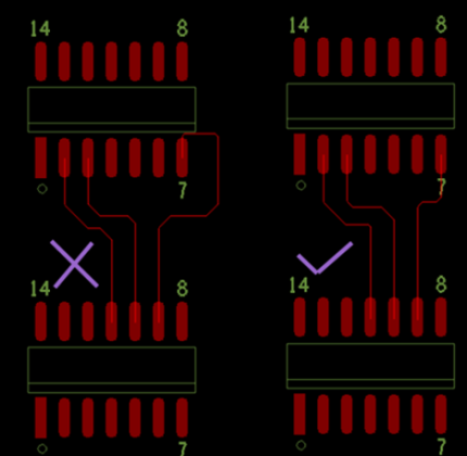
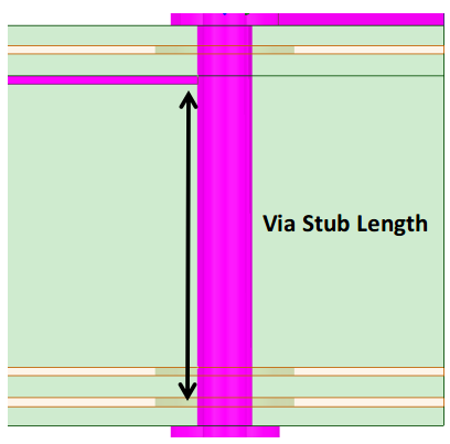
- As shown in the upper figure below, STUB is not allowed in routing. The stub length shall be minimized, and a stub length of zero is recommended. In addition, avoid the via stub effect, especially when the stub length exceeds 12mil, it is recommended to evaluate the impact of the via stub on signal integrity through simulation, as shown in the lower figure below.

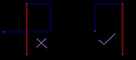
- Try to avoid traces forming self-loops on different layers. This problem is prone to occur in multilayer board design, and self-loops will cause radiated interference, as shown in the figure below.
- It is recommended not to place test points on high-speed signals.
- For signals that generate interference or sensitive signals (such as RF signals), a shielding can must be planned. The width of the shielding can is normally 40mil (generally kept above 30mil, which can be confirmed with the customer's manufacturer). GND vias shall be placed on the shielding can as much as possible to improve its soldering performance.
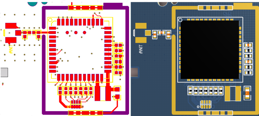
- The routing width of the same net shall be consistent. Variation in trace width will cause non-uniform characteristic impedance of the line, resulting in reflection when the transmission speed is high. Under certain conditions, such as the lead-out lines of connectors and BGA packages, it may be impossible to avoid trace width changes due to too small spacing. In this case, the effective length of the inconsistent part in the middle should be minimized as much as possible, as shown in the figure below.

- The trace width exiting from IC pins shall be less than or equal to the pad width, and the exit width shall not be larger than the pad width. For some signals requiring a wider line width due to current carrying requirements, the routing can first keep the same width as the pin, and then widen the line width about 6-10mil after exiting the pad, as shown in the figure below.
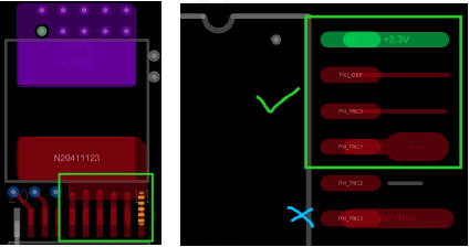
- Routing must be connected to the center of pads and vias.
- For high-voltage signals, the creepage distance must be guaranteed. The specific parameters are shown in the table below.
| 1) Creepage Distance |
|
2) Clearance |
| I. General AC-DC Power Supply (120VAC-240VAC) |
|
|
| L-N |
3.2 before fuse |
2.5 |
|
2.5 after fuse |
2.0 |
| Primary to Ground |
3.4 |
2.5 |
| Before Rectifier Bridge |
2.5 |
2.0 |
| After Rectifier Bridge |
2.5 |
2.0 |
| Fuse |
3.2 |
2.5 |
| Ground to MOS (Switch Tube) |
4.0 |
2.8 |
| Primary to Secondary |
8.0 |
5.0 |
| Secondary to Ground |
1.4 |
0.7 |
| II. AC-DC with PFC Circuit |
|
|
| Primary to Ground |
4.5 |
2.7 |
| Primary to Secondary |
9.0 |
5.4 |
| III. DC-DC Power Supply Above 60V and Below 100V |
|
|
| Primary to Secondary |
3.5 |
2.0 |
| Primary to Ground |
1.8 |
1.0 |
| V+ V- Before Fuse |
1.8 |
1.0 |
- For designs including multiple DDR or other memory chips, the routing topology must be confirmed with the customer, and the existence of reference documents must be verified.
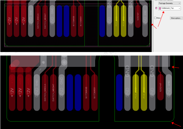
- The gold finger area requires full window opening treatment. In multilayer board design, the copper on all layers under the gold finger shall be hollowed out, and the distance between the hollowed-out copper and the board frame is generally more than 3mm.
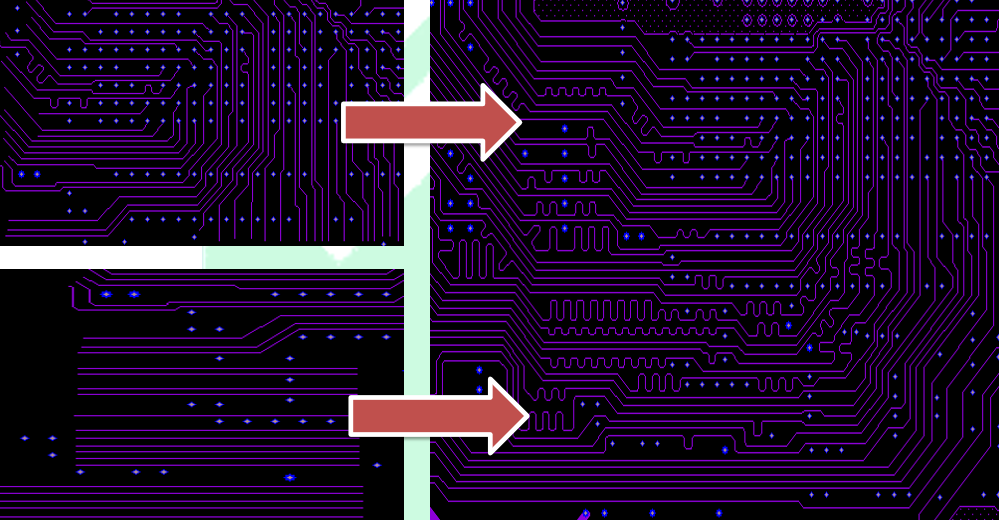
- For routing, the channel condition at the bottleneck position shall be planned in advance, and the routing capacity at the narrowest part of the channel shall be reasonably planned.
- Coupling capacitors shall be placed as close to the connector as possible.
- Series resistors shall be placed close to the transmitting end device, and termination resistors shall be placed close to the receiving end. For example, the series resistor on the eMMC clock signal is recommended to be placed close to the CPU side (within 400mil).
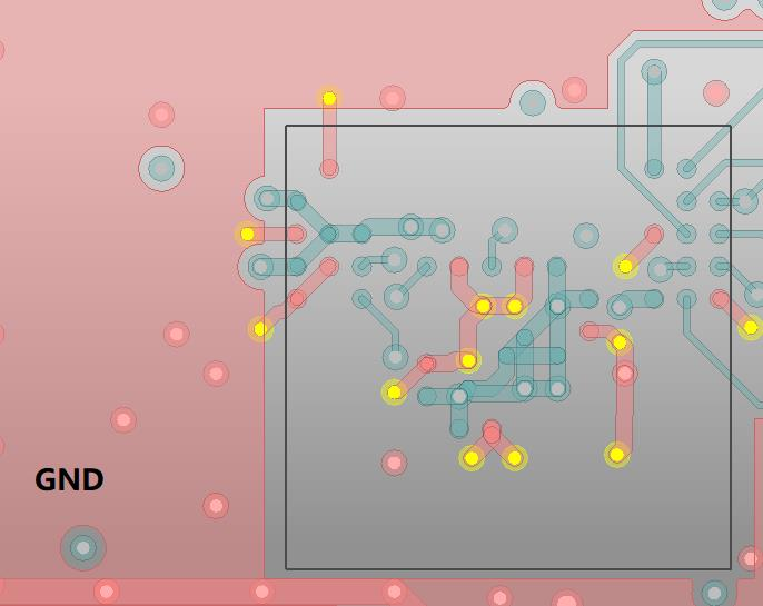
- It is recommended to place one ground via for each ground pad of ICs (such as eMMC chips, FLASH chips, etc.) to effectively shorten the return path, as shown in the figure below.
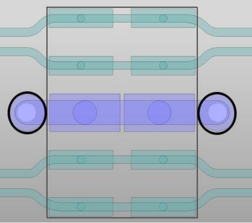
- It is recommended to place one ground via for each ground pad of the ESD device, and the via shall be as close to the pad as possible, as shown in the figure below.
- Avoid routing around clock devices (such as crystals, oscillators, clock generators, clock distributors), switching power supplies, magnetic components, and through-hole vias of connectors.
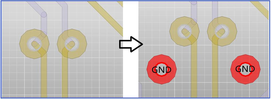
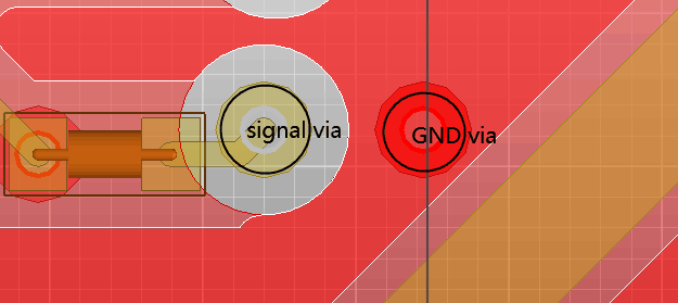
- When traces switch layers, and the reference layers before and after layer transition are ground planes, an accompanying ground via shall be placed next to the signal via to ensure the continuity of the return path. For differential signals, signal vias and return vias shall be placed symmetrically, as shown in the upper figure below; for single-ended signals, it is recommended to place a return via next to the signal via to reduce crosstalk between vias, as shown in the lower figure below.
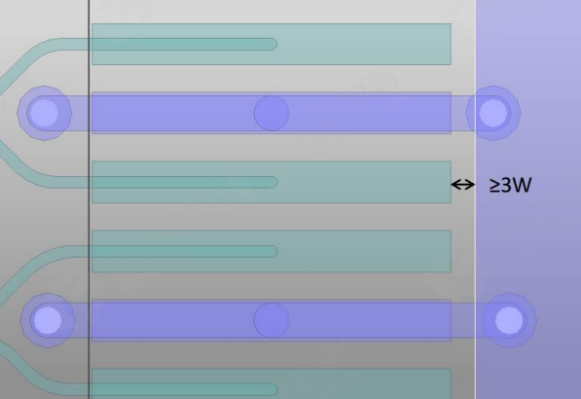
- The ground copper of the connector shall be at least 3 times the line width away from the signal PAD, as shown in the figure below.
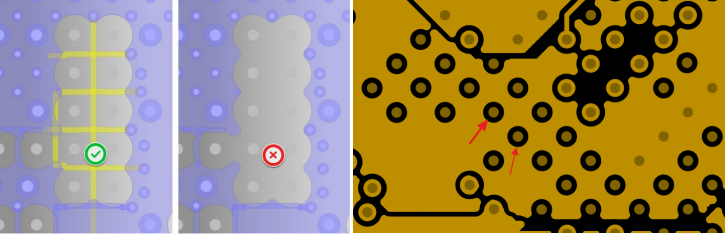
- At the plane break in the BGA area, connect with traces or perform pad trimming to avoid damaging the plane integrity, as shown in the figure below.
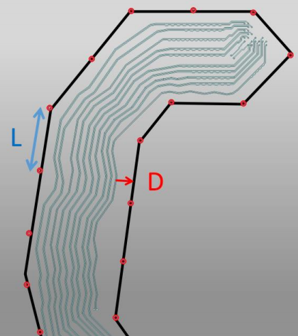
- When PCB routing requires ground wrapping treatment, the recommended ground wrapping method is as shown in the figure below, where L is the ground via interval on the ground wrapping trace; D is the distance between the ground wrapping trace and the signal line, recommended ≥4*W.
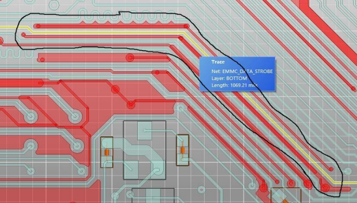
- For some important high-speed single-ended signals, such as clock signals, reset signals (e.g., emmc_clk, emmc_datastrobe, RGMII_CLK, etc.), ground wrapping is recommended. At least one ground via shall be placed every 500mil on the ground wrapping trace, as shown in the figure below.
About Maxipcb
Maxipcb empowers innovators to turn cutting-edge technologies into reality.
We offer one-stop solutions for design, simulation, testing, PCB manufacturing, component procurement and SMT assembly, enabling efficient development, rapid deployment and risk control across the full product lifecycle.Serving the world in communications, industrial automation, aerospace, automotive, semiconductor and beyond, we build a safer, more connected future together.
