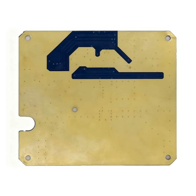
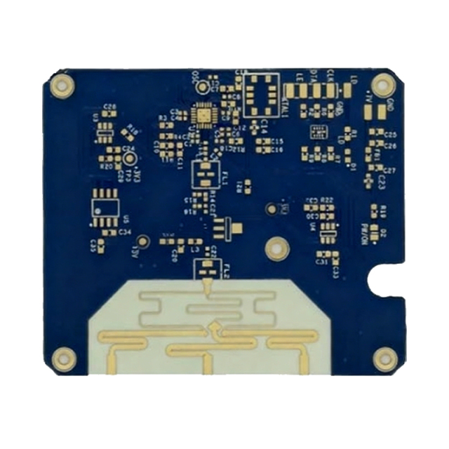
• Rogers RO3003 High Frequency PCB Board
  • Rogers RO3003 High Frequency PCB Board
  • Rogers RO3003 High Frequency PCB Board
  • Rogers RO3003 High Frequency PCB Board

Rogers RO3003 High Frequency PCB Board

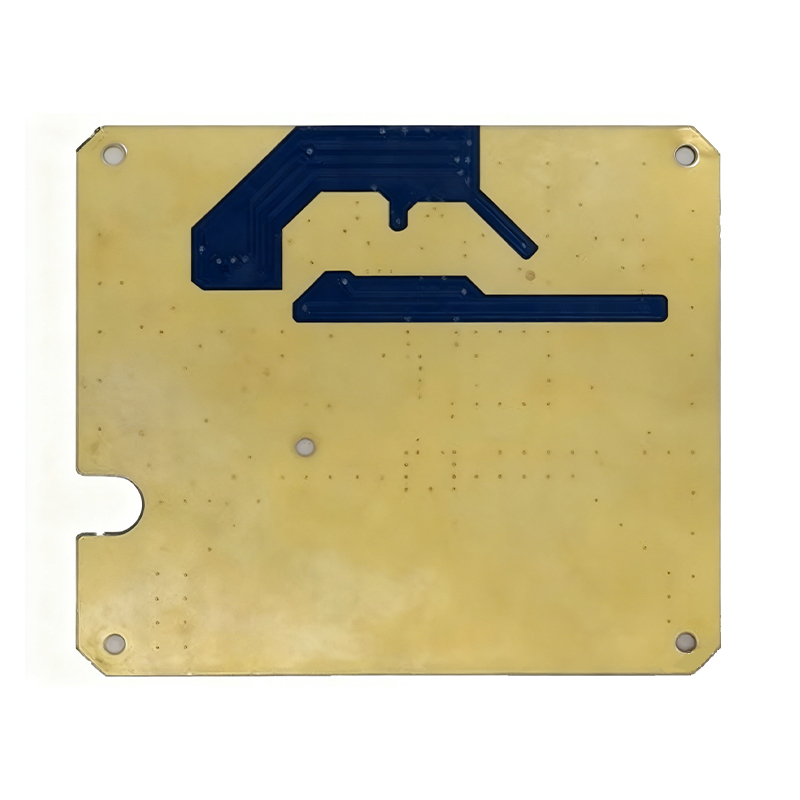
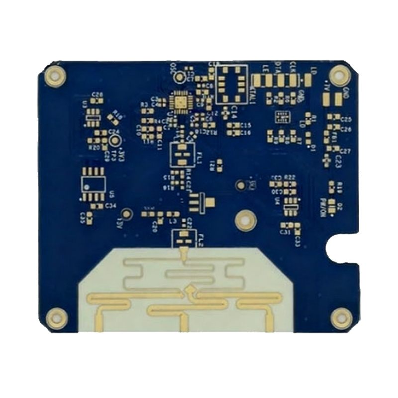
Product Model: Rogers RO3003 High-Frequency PCB
Material: Rogers RO3003 substrate
Layer Count: 2 Layers
Dielectric Constant (DK): 3.0
Dielectric Thickness: 0.75mm
Thermal Conductivity: 0.5 W/m·K
Finished Thickness: 0.9mm
Copper Thickness: 1oz
Surface Treatment: Immersion Gold
Application: Automotive radar PCB, RF coupler PCB, cost-sensitive aviation PCB, GPS antenna PCB

  • Rogers RO3003 High Frequency PCB Board
  • Rogers RO3003 High Frequency PCB Board
  • Description

  • Data Sheet

1. Overview of Rogers RO3003 High-Frequency Circuit Material

Rogers RO3003 is a high-performance ceramic-filled polytetrafluoroethylene (PTFE) composite material, specifically developed for commercial microwave and radio frequency (RF) applications. It is engineered to deliver superior electrical and mechanical stability while maintaining competitive pricing, making it a cost-effective choice for a wide range of high-frequency PCB projects.


2. Core Performance Parameters

RO3003 exhibits excellent high-temperature resistance and stable electrical performance, specifically reflected in the following key parameters:
  • High-temperature adaptability: It performs stably at 10GHz within a wide temperature range of -50℃ to +150℃, adapting to diverse harsh working environments.
  • Dielectric constant (DK) temperature coefficient: The DK temperature coefficient is -3 ppm/℃, ensuring minimal fluctuation of dielectric constant with temperature changes.
  • Permittivity frequency stability: It maintains high permittivity frequency stability, enabling reliable operation across a wide frequency range.
  • Low dielectric loss (DF): At 10GHz, RO3003 laminates show an extremely low dielectric loss factor of 0.0013, effectively reducing signal attenuation during high-frequency transmission and ensuring signal integrity.

3. Key Characteristics of Rogers RO3000 Series Laminates

As a core member of the Rogers RO3000 series, RO3003 inherits the series’ outstanding overall performance. The RO3000 series laminates are all ceramic-filled PTFE-based circuit materials, with consistent mechanical properties regardless of the selected dielectric constant. This unique advantage allows designers to develop multi-layer PCB designs that adopt different dielectric constant materials for individual layers, without encountering warpage or reliability issues during manufacturing or use.
In terms of thermal expansion performance, the RO3000 series exhibits a thermal expansion coefficient (CTE) of 17 ppm/℃ in the X and Y axes, which perfectly matches the CTE of copper. This matching ensures excellent dimensional stability of the material, with a typical etching shrinkage (after etching and baking) of less than 0.5 mils/inch. The Z-axis CTE is 24 ppm/℃, providing excellent plated through-hole (PTH) reliability even in harsh thermal environments, effectively extending the service life of multi-layer PCBs.
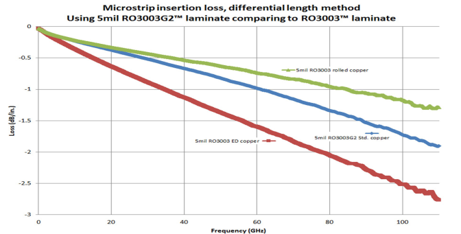
Additionally, RO3003 Gamma and RO3035 Gamma variants within the series feature extremely stable relationships between dielectric constant and temperature (see Figure 1), further enhancing their adaptability in temperature-fluctuating scenarios.

4. Processing Technology & Quality Certification

The RO3000 series laminates can be fabricated into printed circuit boards using standard PTFE circuit board processing techniques, with only minor modifications required as specified in the application guide "Manufacturing Guidelines for RO3000 Series High-Frequency Circuit Materials". This simplifies the manufacturing process, reduces processing difficulty, and improves production efficiency.
All RO3000 series laminates, including RO3003, are manufactured under the ISO 9001 certification system, ensuring strict quality control throughout the production process and consistent performance of batch products.

5. RF/Microwave PCB Application Overview

Radio frequency (RF) printed circuit boards (PCBs) have become an increasingly indispensable technology in the PCB industry, with their application scope expanding rapidly alongside the development of new electronic technologies. They are classified based on operating frequency:
  1. RF PCBs: Operate at frequencies above 100 MHz, suitable for a variety of general high-frequency electronic devices and communication systems.
  2. Microwave PCBs: Operate at frequencies above 2 GHz, mainly used in high-frequency communication, radar, and microwave equipment.
RF PCBs are widely applied in various fields, including remote controls (wireless controls), security systems, smartphones, sensors, and other electronic products. The continuous advancement of new technologies such as 5G, GPS, and radar systems has further increased the demand for RF applications, which in turn imposes higher requirements on PCB manufacturing quality standards and material selection.
Understanding the properties of various RF materials is crucial for PCB manufacturing. Choosing the right material—such as Rogers RO3003 for cost-sensitive, high-performance scenarios—is perhaps the most critical decision in the production process of RF PCBs, as it directly determines the performance, reliability, and cost-effectiveness of the final product.

6. Typical Applications of Rogers RO3003

Leveraging its excellent electrical and mechanical stability, competitive pricing, and wide environmental adaptability, Rogers RO3003 is widely applied in the following fields:
  • Radar PCBs
  • RF coupler PCBs
  • Cost-sensitive aerospace PCBs
  • GPS antenna PCBs

Model: Rogers RO3003 high-frequency PCB

Material: Rogers RO3003

Layer: 2L

DK:3.0

Medium thickness: 0.75MM

Thermal conductivity: 0.5w/m.k

Finished product thickness: 0.9MM

Copper thickness: 1OZ

Surface treatment: gold immersion

Application: automobile radar PCB, RF coupler PCB, cost-sensitive aviation PCB, GPS antenna PCB