With the rapid progress of the communication industry, the original civil communication frequency bands are crowded, and some high-frequency communication frequency bands (military) are gradually transferred to civil use. Civil high-frequency communication has achieved unconventional rapid development, and is widely used in satellite reception, base stations, navigation, medical treatment, transportation and other fields.
With the rapid progress of the communication industry, the original civil communication frequency bands are crowded, and some high-frequency communication frequency bands (military) are gradually transferred to civil use. Civil high-frequency communication has achieved unconventional rapid development, and is widely used in satellite reception, base stations, navigation, medical treatment, transportation and other fields.
High confidentiality and high transmission quality require mobile phones, automotive power stations, and wireless communications to develop toward high frequency. High picture quality requires high-frequency broadcasting for radio and television transmission. High-information-volume information transmission requires high-frequency for satellite communications, microwave communications, and optical fiber communications.
The improvement of computer technology processing capacity and the increase of information storage capacity urgently require high-speed information transmission. Therefore, the high-frequency and high-speed development of electronic information products puts forward requirements for high-frequency characteristics of PCBs.
Part.1 Requirements for High-Frequency and High-Speed Materials
- Low Dielectric Constant (Low Dk): Low dielectric constant can improve signal transmission speed.
- Low Dissipation Factor (Low Df): As frequency increases, intensity loss also increases. Therefore, materials with low dissipation factor are mostly used in the design and manufacturing of high-frequency and high-speed communications.
- Conductor Surface Roughness: The higher the signal frequency, the more obvious the skin effect. Therefore, the flatter the surface of the signal transmission conductor, the better.
εeff: Effective dielectric constant
tanδ: Dissipation factor
f: Frequency
c: Light speed
Part.2 Dielectric Constant: Dk or Er (ε)
It refers to the amount of electrostatic energy that an insulating material per "unit volume" can store under each unit of "potential gradient". The smaller the dielectric constant (or permittivity) of the insulating material, the better. Among current substrates, PTFE (Teflon) has the best dielectric constant of 2.5 at 1 MHz, and FR-4 is about 4.7. A circuit board can be regarded as a capacitor device. When signals are transmitted in the wires, part of the energy will be accumulated by the circuit board, causing transmission delay, and the delay becomes more obvious with higher frequency.
Part.4 Dissipation Factor: Df
It is a measure of functional loss of alternating current, and a characteristic of insulating materials (resins). It is proportional to the electrical power loss observed, and inversely proportional to the cyclic frequency (f), the square of the potential gradient (E²), and the unit volume.
Part.5 Conductor Surface Roughness
The morphology of conductor surface roughness causes resistance heating and signal energy loss, which is called conductor loss. The higher the frequency and the shorter the wavelength, signals traveling between conductors will only concentrate on the surface of the conductors, namely the skin effect. A flatter surface roughness is more beneficial to signal transmission. The bonding strength between PCB layers is affected by conductor surface roughness. The higher the conductor surface roughness, the larger the bonding area between resin and conductor, and the higher the bonding strength.
Part.6 Copper Foil
Classified by Manufacturing Process
- Electrodeposited Copper Foil
Advantages: Low cost; available in various sizes and thicknesses.
Disadvantages: Poor ductility; extremely high stress, unable to bend and easy to break.
- Rolled-Wrought Copper Foil
Advantages: High ductility, excellent reliability for FPC used in dynamic environments; low surface ridges, beneficial for microwave electronic applications.
Disadvantages: Poor adhesion to substrates; high cost; limited width due to technical problems.
Classified by Copper Foil Performance
High-temperature elongation copper foil, reverse-treated copper foil, double-sided treated copper foil, ultra-low ridge copper foil, ultra-thin copper foil, standard electrodeposited copper foil.
Part.7 How PP is Manufactured
PP is the abbreviation of Prepreg, and "Prepreg" is the short form of "preimpregnated".
Taking epoxy resin as an example, liquid resin added with cross-linking agent (hardener), accelerator, solvent, and sometimes filler is called varnish or A-stage resin. Adding fillers is mainly to improve the flame retardancy of the resin and adjust its Tg (glass transition temperature) at the same time. Glass fiber filaments or other fiber filaments are impregnated with A-stage resin and then partially thermally polymerized to form PP (B-stage resin: solid state).
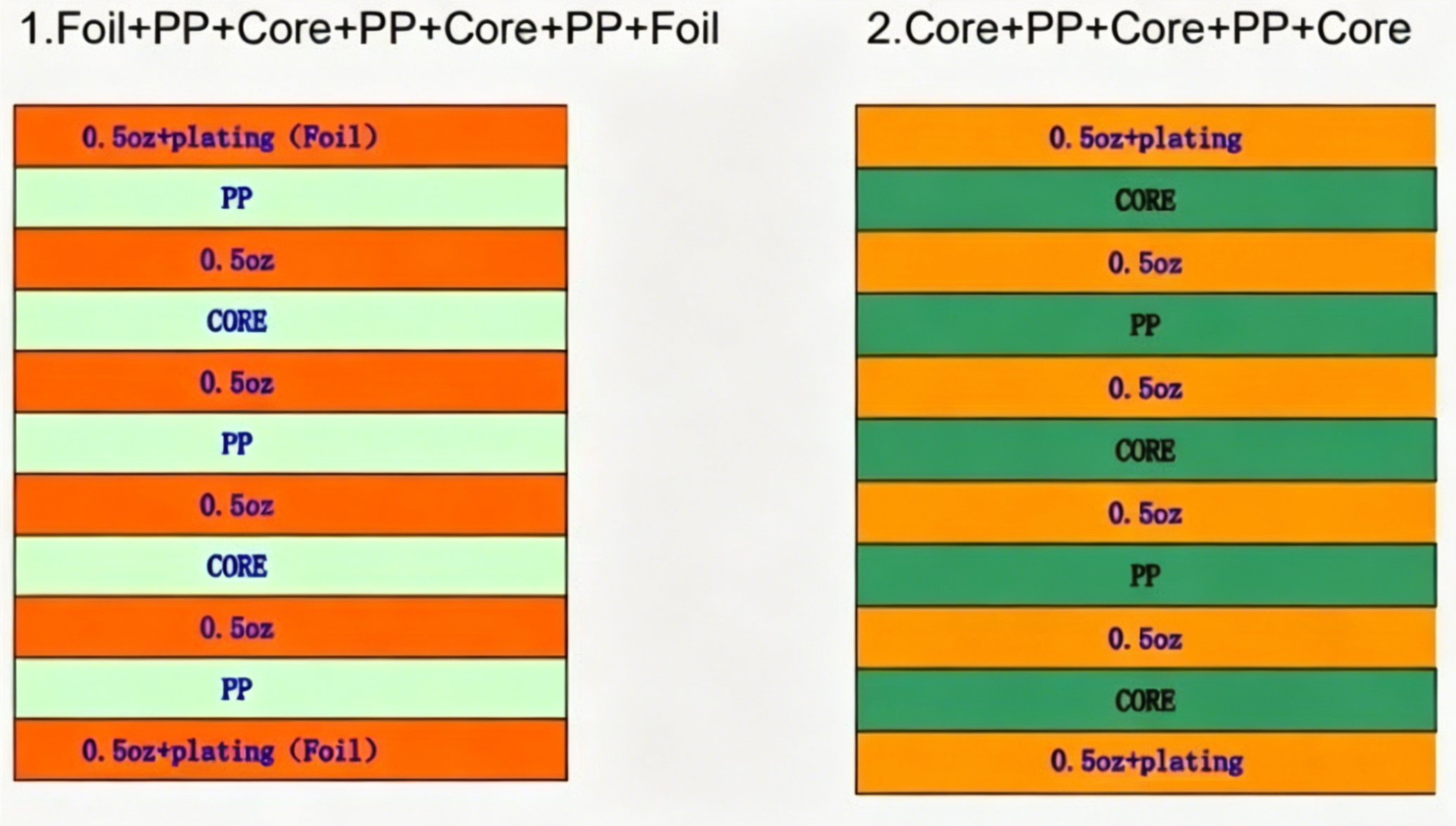
- Foil + PP + Core + PP + Core + PP + Foil
- Core + PP + Core + PP + Core
 About Maxipcb
Maxipcb empowers innovators to turn cutting-edge technologies into reality.
We offer one-stop solutions for design, simulation, testing, PCB manufacturing, component procurement and SMT assembly, enabling efficient development, rapid deployment and risk control across the full product lifecycle.Serving the world in communications, industrial automation, aerospace, automotive, semiconductor and beyond, we build a safer, more connected future together.
