
This document was written based on practical observations of electromagnetic interference from high-speed signals and power switching, which can cause process failures. Layout and schematic design recommendations for components used in a product may be provided in datasheets, but actual observations and solutions may differ.
This document covers high-speed signals such as HDMI, MIPI CSI, MIPI DSI, and Ethernet. Emissions at frequencies above 9 kHz should be within the limits set by the standard. Emissions from devices are usually multiple harmonics of high-frequency clocks on the PCB. Single-ended clocks radiate more than differential clocks because single-ended signals have higher voltage levels and power. It is strongly recommended to use a 0-ohm series resistor at the source of any high-speed single-ended clock.
During this process, increasing the series resistance value helps control the overshoot and undershoot present in the clock, which are the main causes of radiation. Increasing the value of the series resistor helps reduce overshoot and undershoot. The value of the series termination resistor can be determined by the receiver's setup and hold time violations. It is also recommended not to use duplicate frequencies where possible.
For example, if two switching regulator parts are used as power regulators, make sure that neither operates at the same switching frequency, because the sum of their emissions will exceed the prohibited radiation limits. The longer the clock signal length, the greater the radiated power. For example, a longer HDMI cable will act as an antenna, so in this case the radiation from the HDMI interface will be higher.
Layout plays an important role in radiation. Ensure that clock signals are designed to meet characteristic impedance requirements and have continuous grounding around the clock traces to avoid impedance mismatch. Follow the chip manufacturer's layout guidelines very accurately, and ensure that the manufacturer reviews the schematic and layout of that specific part from a radiation perspective. Chip manufacturers may make some recommendations for new designs based on their experience with chip-related failures.
-
HDMI (High-Definition Multimedia Interface)
EMI failures caused by HDMI interfaces are common in embedded products. HDMI radiation appears on the fundamental and usually up to the subharmonics of 148.5 MHz, 297 MHz, 445.5 MHz, 594 MHz, 742.5 MHz, and 891 MHz.
The radiation source may come from the HDMI cable, the PCB design, or the monitor itself (if it has not been tested). Common-mode chokes and termination resistors/capacitors should help eliminate radiation on the PCB, but common mistakes occur in HDMI cable selection. Different cables from different manufacturers provide different emission levels, even if they are shielded. Therefore, it is important to choose cables from trusted suppliers such as Molex or TE. Of course, the selected cable should be shielded and have a built-in ferrite core. It is recommended to carry 3–4 different cables (from different brands) for pre-scanning to verify the performance of each cable.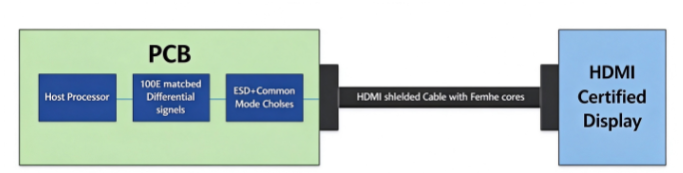
The following techniques can help reduce radiation from HDMI signals:
-
The common-mode choke should be selected with a cutoff frequency 5–6 times higher than the fundamental frequency. For 148.5 MHz, a cutoff frequency above 1 GHz should be ideal.
-
Differential signals transitioning from one layer to another should ensure that ground vias are adjacent to the signal to reduce loop inductance.
-
In the case of HDI PCBs, ground vias should be routed down alongside the signal to provide a short return path to the source.
-
The metal enclosure should use a good grounding scheme, using shielded connectors to properly terminate the cable shield to the enclosure to reduce interference.
-
In the case of reference planes at different potentials (ground and power), bypass capacitors are recommended.
-
Other general guidelines, such as length matching (10 mil intra-pair and 100 mil inter-pair), impedance matching (100 ohms), solid reference planes, microstrip routing, fewer vias, and 45-degree bends, are practices to be followed.
-
MIPI DSI and CSI (Mobile Industry Processor Interface)
MIPI signals (CSI/DSI) are designed for the mobile industry, so they are very low-power differential signals and are less likely to radiate. The MIPI signal clock varies depending on resolution parameters.
Radiation may occur on FPC cables carrying MIPI signals. In the case of custom cables, adding shielding or grounding on both sides can help immediately, but it may affect cable flexibility. The method is to use a hatched ground on the directly adjacent layer as the reference ground. A higher-bandwidth off-the-shelf common-mode choke will help eliminate common-mode noise on the PCB. The data rate of MIPI signals is 80 Mbps–2.5 Gbps for D-PHY and 183 Mbps–5.7 Gbps for C-PHY. Therefore, it is important to provide a guard ring and at least 40 mil isolation from other signals.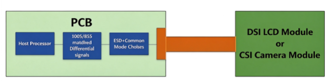
The following techniques can help reduce radiation from MIPI signals:
-
Select a common-mode choke with a cutoff frequency above 2 GHz for D-PHY. C-PHY can use a special filter to pass the trio signals.
-
Differential signals transitioning from one layer to another should ensure that ground vias are adjacent to the signal to reduce loop inductance.
-
In the case of HDI PCBs, ground vias should be routed down alongside the signal to provide a short return path to the source.
-
If there is an EMI film on the FPC, ensure that the end of the film is connected to the exposed signal ground on the FPC.
-
In the case of reference planes at different potentials (ground and power), bypass capacitors are recommended.
-
Other general guidelines, such as length matching (25 mil intra-pair and 55 mil inter-pair), impedance matching (100 ohms/85 ohms in a few cases), solid reference planes, microstrip routing, fewer vias, and 45-degree bends, are practices to be followed.
-
Ethernet
Radiation on Ethernet signals is proportional to the length of the twisted-pair cable. Shielded CAT5 cable and ferrite cores on the cable will help reduce interference.
Differential MDI signals radiate when common-mode noise on the cable returns through chassis ground.
Noise from single-ended MII and the power supply section can couple to the twisted-pair cable through chassis ground, producing unwanted radiation.
The following techniques can help reduce radiation from Ethernet signals:
-
Ferrite cores on Ethernet cables can reduce EMI. Keep different types of CAT5 cables during the process.
-
MDI signals should be well isolated from MII signals (at least 40 mil apart).
-
Maintain the length of single-ended MII signals.
-
Keep the void under the magnetic components in all layers.
-
MDI and MII signals transitioning from one layer to another should ensure that ground vias are located near the signal to reduce loop inductance.
-
In the case of HDI PCBs, ground vias should be routed down alongside the signal to provide a short return path to the source.
-
The metal enclosure should use a good grounding scheme, and the cable shield should be properly terminated to the enclosure using shielded RJ45 connectors to reduce interference.
-
In the case of reference planes at different potentials (ground and power), bypass capacitors are recommended.
-
Other general guidelines, such as length matching (10 mil intra-pair and 100 mil inter-pair), impedance matching (100 ohms), solid reference planes, microstrip routing, fewer vias, and 45-degree bends, are practices to be followed.
-
DC-DC Power Generation
For high-speed PCB design, a noisy power supply is one of the main contributors to EMI-EMC radiation. A stable and less noisy power supply definitely helps reduce EMI.
Processors, memories, and bridge chips used for high-speed interfaces operate at very low voltages. DC-DC switching regulators are selected in designs to obtain high output current and efficiency. However, the switching frequency and the ripple (overshoot and undershoot) noise generated by these switches also cause radiation. Coupling of noisy signals into ground increases radiation because the ground will move together with the cable, and the cable can act as an antenna for high-frequency noise.
If the actual system power consumption is high (>10 W) and long cables are involved in the product, it is recommended to use a common-mode choke and LC filtering on the input DC power supply. Online calculators can be used to calculate the L and C values for the specific frequency at which radiated power needs to be attenuated. The higher the inductance value, the less spatial constraint there is.
Generally, the high-frequency (ringing) observed at the overshoot and undershoot of the switching frequency is more likely to radiate.
Snubber tuning will help reduce this overshoot and undershoot power. Use larger packages or high-power-rated resistors, because high-frequency noise will be bypassed, and smaller packages may increase the PCB temperature. The snubber circuit should be installed at the inductor's switching node.
Key Points to Remember for High-Speed PCB Design
-
Surface-mount parts should be preferred over through-hole parts. Through-hole components such as capacitors become more inductive above 80 MHz, which may cause radiation/sorting problems at higher frequencies.
-
Keep high-speed signal traces as small as possible and provide grounding as much as possible to reduce loop inductance.
-
Try to avoid stacking adjacent signal layers, or use orthogonal routing to reduce capacitive coupling.
-
Place decoupling capacitors very close to IC pins. This will help switch between power and ground more quickly.
-
Use star routing for signals and single-point routing for power.
-
Use ferrite beads on power outputs. Placing capacitors around the ferrite bead will act as a low-pass filter for high-frequency noise.
-
Keep a 0Ω series termination resistor at each clock output whose output is >1 MHz. This will help with adjustment if interference problems occur.
-
For crystals, select parallel capacitors that account for load and stray capacitance according to the datasheet. They are fundamental to radiation, so follow the IC recommendations for crystal routing. Also, try to keep the crystal/oscillator at the center of the PCB rather than at the edge.
-
Traces at the PCB edge should not be routed at 90-degree angles.
-
Retain the shielding configuration for the RF section. This is a mandatory requirement for FCC (modular).
-
High-frequency square waves are composed of multiple high-frequency sine waves. Therefore, ensure that critical signals of this type have appropriate grounding around them.
-
Ensure that, for continuous ground layers, vias do not connect islands to very thin copper areas. This can increase the ground return path for signals.
-
FR4 material has <5 Gbps clock speed and low cost. For above 5 Gbps, use other materials such as Nelco, Megatron, and Rogers.
-
Maintain >3W spacing from other signals for high-speed signals.
-
Compared with the ground plane, the power plane should be inset from the PCB edge. As a rule of thumb, this is 20H (H = dielectric thickness between layers).
Summary
This document is based on practical observations of EMI reduction in high-speed PCB design. EMI preventive measures are very helpful. Radiation from high-speed interfaces varies from design to design, so it is recommended to include provisions in the design that facilitate adjustment during the process.
This document introduces precautions for high-speed signals commonly used on PCBs. EMI problems caused by HDMI interfaces have been observed in almost all products. Series termination, parallel termination, and chokes do not help much in reducing radiation. Variations in HDMI cables and HDMI monitors will change radiated power. Long cables will act as antennas for high-speed interfaces, so if multiple long cables are connected to a product (e.g., automotive products), many precautions need to be taken.