When implementing temperature sensing on a PCB, many engineers encounter the same issues: the datasheet parameters look excellent, but in practice the deviation is large, consistency is poor, and response is slow. The problem often lies not with the sensor itself, but with three key factors: the thermal path, the pad design, and the mechanical structure.
When implementing temperature sensing on a PCB, many engineers encounter the same issues: the datasheet parameters look excellent, but in practice the deviation is large, consistency is poor, and response is slow. The problem often lies not with the sensor itself, but with three key factors: the thermal path, the pad design, and the mechanical structure. This article takes a practical approach to explain how to minimise temperature measurement errors through proper component selection and thermal design.
Let us start with the most common mistake: using a standard SMD sensor that relies solely on two small pads for thermal conduction. Heat must travel through the package → air → small pads → PCB, resulting in a huge thermal resistance. Not only is this slow, but it is also highly susceptible to airflow. What you end up measuring is not the true node temperature, but a "mixed air temperature."
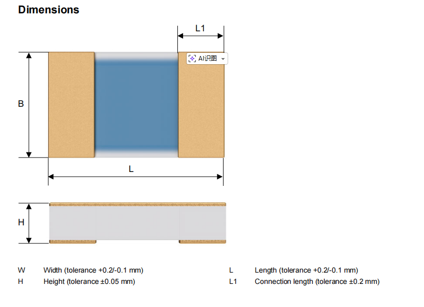
The JUMO 906146 is well‑suited for high‑precision PCB temperature measurement because of its backside fully metallised solderable structure. It is not a "point‑contact" but a surface‑contact thermal path. The sensor backside bonds tightly to the PCB pad via solder, achieving the shortest thermal path and lowest thermal resistance, which dramatically improves response speed and measurement accuracy. In an 0805 package, under 3 m/s airflow, the t₀.₅ is only 8 seconds, allowing it to track rapid temperature changes quickly.
Thermal Design Step 1: The Pad Directly Determines Success or Failure. The recommended pad dimensions for the 0805 package are: A = 0.65 mm, B = 1.25 mm, C = 2.2 mm, D = 0.9 mm. Solder mask defined (SMD) pads are recommended – ensure that no solder mask encroaches onto the pad area, guaranteeing proper wetting. There is no need for extra large copper areas, thermal vias, or thermally conductive adhesive. Following the standard recommendations will achieve stable and compliant performance.
Thermal Design Step 2: Match the PCB Laminate to Avoid Thermal Cycling Failures. The sensor's board‑level operating temperature range is ‑50 °C to +150 °C. Choose a PCB material with a compatible coefficient of thermal expansion (CTE). Under repeated thermal cycling, this minimises stress, prevents solder joint failure, and avoids cracking. This is especially critical for automotive, industrial, and outdoor equipment. In many projects, short lifetimes are not due to sensor limitations, but to incorrect thermal matching.
Thermal Design Step 3: Control Self‑Heating for More Accurate Data. In confined spaces, low airflow, or highly integrated modules, sensor self‑heating can introduce significant errors. The 906146 uses a Pt1000 element. The recommended measurement current is 0.1 mA, and its self‑heating coefficient is only 0.3 °C/mW, resulting in extremely low self‑heating effects. Even in small cavities, it can measure temperatures close to the true value.
Thermal Design Step 4: Reduce Thermal Interference in Multi‑point Acquisition. In BMS, multi‑zone temperature control, and multi‑channel DAQ systems where sensors are densely packed, mutual thermal interference can degrade consistency. This device is small, consumes low power, and generates minimal heat, so its temperature rise impact on surrounding components is negligible – ensuring accurate and consistent readings for every channel.
Finally, emphasise the impact of the assembly process on thermal design: reflow soldering is mandatory – manual hand‑soldering with a soldering iron is prohibited. Hand‑soldering introduces localised overheating and severe thermal shock, which can damage the internal structure and introduce additional stress, leading to unstable thermal resistance and drift in accuracy. Follow the standard SAC305/405 reflow profile to achieve the most stable thermal performance.
Summary: To achieve first‑pass success in PCB temperature measurement, focus on these four points:
-
Choose a sensor with full backside contact to shorten the thermal path.
-
Follow the recommended pad dimensions – do not arbitrarily reduce them.
-
Match the PCB laminate to minimise thermal stress.
-
Use reflow soldering to ensure stable and reliable thermal resistance.
This combination can resolve over 90 % of issues related to "inaccurate measurements, slow response, and poor consistency" – delivering stable results whether in industrial controls, medical devices, automotive systems, or home appliances.
About Maxipcb
Maxipcb empowers innovators to turn cutting-edge technologies into reality.We offer one-stop solutions for design, simulation, testing, PCB manufacturing, component procurement and SMT assembly, enabling efficient development, rapid deployment and risk control across the full product lifecycle.
Serving the world in communications, industrial automation, aerospace, automotive, semiconductor and beyond, we build a safer, more connected future together.
