When designing PCBs, we often rely on experience and tips found online. Some rules are universal, while others apply only to specific designs – for example, rules for an ADC board may not be suitable for an RF board, and vice versa. However, certain guidelines can be considered universal for any PCB design. Today we look at some methods and techniques that can significantly improve the basic issues of PCB design.
When designing PCBs, we often rely on experience and tips found online. Some rules are universal, while others apply only to specific designs – for example, rules for an ADC board may not be suitable for an RF board, and vice versa. However, certain guidelines can be considered universal for any PCB design. Today we look at some methods and techniques that can significantly improve the basic issues of PCB design.
Power and Signal Distribution
Power distribution is a critical element in any electrical design. All components rely on the power supply to function. Depending on your design, some components may have a good power connection, while others on the same board may have a poor one.
For instance, if all components are powered by a single trace, each component will see a different impedance, leading to multiple ground references. If you have two ADC circuits – one at the beginning and one at the end – both reading an external voltage, each analog circuit will read that voltage relative to its own distinct potential.
We can summarise power distribution in three possible ways: single‑point source, star source, and multi‑point source.
(a) Single‑point power source:
The power and ground traces for each component are separate from each other, and they meet only at a single reference point. This single point is considered optimal for power distribution. However, for complex or medium‑to‑large projects, this is not feasible.
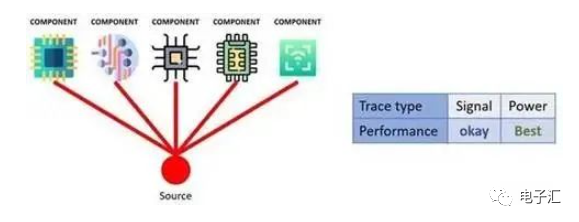
(b) Star source:
The star source can be seen as an improvement over the single‑point source. It differs due to a key characteristic: the trace lengths between components are equal.
Star connections are often used on complex high‑speed signal boards with multiple clocks. In high‑speed signal PCBs, signals typically come from the edges and go to the centre. All signals can go from the centre to any area of the board, and the delays between regions are [intentionally minimised/balanced].
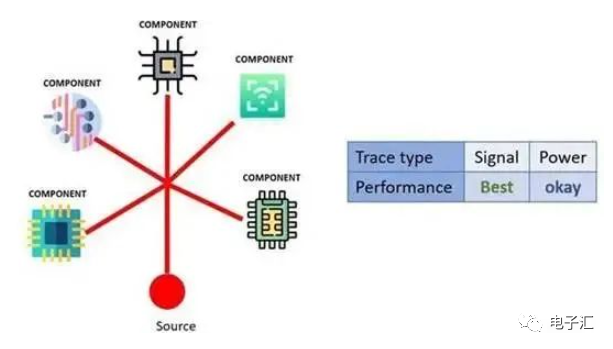
(c) Multi‑point source:
This is considered the worst design type in any situation, yet it is easy to use in any circuit. A multi‑point source can create reference differences between components as well as common‑impedance coupling problems.
This design style also allows high‑frequency switching ICs, clocks, and RF circuits to inject noise into nearby circuits sharing the same connection.
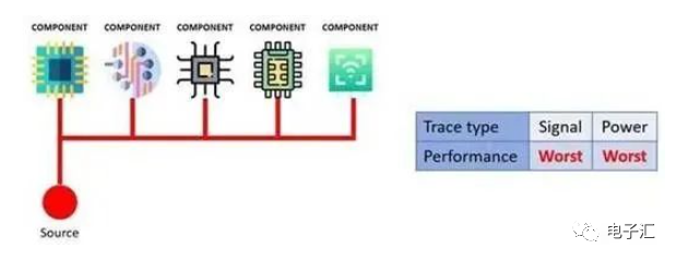
Of course, in our daily work, we cannot always have a single distribution type. The compromise we can make is to mix a single‑point source with a multi‑point source. Sensitive analog devices and high‑speed/RF systems can be placed in one point, while all other less sensitive peripherals are placed in another.
Power Planes
Have you ever wondered whether you should use a power plane? The answer is yes. A power plane is one of the methods to deliver power and reduce circuit noise.
A power plane shortens the return path, reduces inductance, and improves electromagnetic compatibility (EMC) performance. In addition, the power plane on both sides forms a parallel‑plate decoupling capacitor, which helps prevent noise propagation.
There is another clear advantage: because of its larger area, the power plane allows higher current flow, thereby increasing the PCB's operating temperature range. But be careful: while power planes improve thermal performance, trace routing must also be considered. Trace design rules are given by IPC‑2221 and IPC‑9592.
For PCBs with RF sources (or any high‑speed signal applications), a solid ground plane is essential to improve board performance. Signals must be on different planes, and with a two‑layer board it is almost impossible to meet both requirements at the same time.
If you are designing an antenna or any low‑complexity RF board, a two‑layer board can be used. The figure below shows how a PCB can better use these planes.
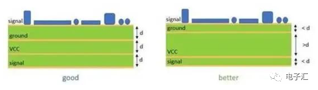
In mixed‑signal designs, it is common practice to separate analog ground from digital ground. Sensitive analog circuits are easily affected by high‑speed switching and signals; if analog and digital grounds are different, the ground planes will be split.
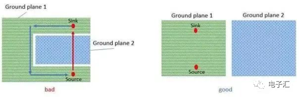
However, there are drawbacks to be aware of, mainly crosstalk and loop areas caused by discontinuities in the ground plane.
The figure below shows an example of two separate ground planes. On the left, the return current cannot flow directly along the signal trace, resulting in a loop area, whereas on the right the design avoids such a loop area.
Electromagnetic Compatibility (EMC) and Electromagnetic Interference (EMI)
For high‑frequency designs such as RF systems, EMI can be a major drawback. The ground planes discussed earlier help mitigate EMI, but depending on your PCB, they may introduce other issues. In stack‑ups with four or more layers, the distance between planes is critical.
When the inter‑plane capacitance is small, the electric field spreads over the board. At the same time, the impedance between the two planes decreases, allowing return current to flow onto the signal plane. This will generate EMI on any high‑frequency signal crossing the planes.
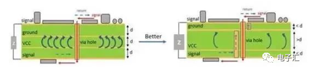
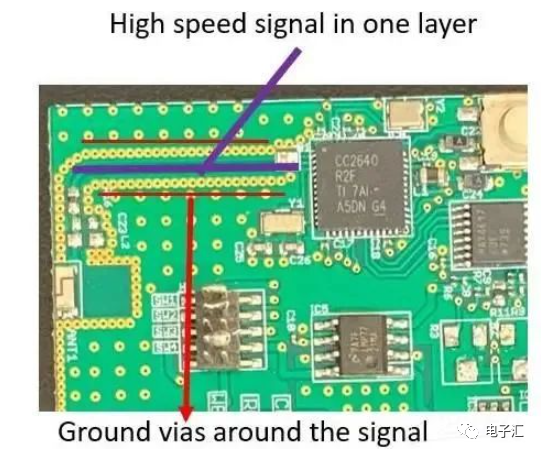
A simple solution to avoid EMI is: prevent high‑speed signals from crossing layer splits; add decoupling capacitors; and place ground vias around signal traces. The figure below shows a good PCB design for high‑frequency signals.
Filtering Noise
Bypass capacitors and ferrite beads are components used to filter noise generated by any device. Basically, any I/O pin can become a noise source if used in high‑speed applications. To make better use of these components, we need to keep the following points in mind:
-
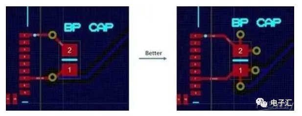
Always place ferrite beads and bypass capacitors as close as possible to the noise source.
-
When using auto‑placement and auto‑routing, check the placement against the distance criteria.
-
Avoid vias and any other routing between the filter and the component.
-
If a ground plane is available, use multiple vias to properly ground the filter.
About Maxipcb
Maxipcb empowers innovators to turn cutting-edge technologies into reality.
We offer one-stop solutions for design, simulation, testing, PCB manufacturing, component procurement and SMT assembly, enabling efficient development, rapid deployment and risk control across the full product lifecycle.
Serving the world in communications, industrial automation, aerospace, automotive, semiconductor and beyond, we build a safer, more connected future together.
