-
In PCB design, to ensure the total length of all signal lines in a group meets the specified tolerance range, serpentine routing is usually used to extend the shorter signal lines to match the length of the longest signal line in the group within the tolerance. This process of extending signal lines with serpentine routing is commonly known as PCB signal length matching. The goal of length matching is to meet the timing matching requirements of signals in the same group.
-
The length matching range shall strictly comply with the requirements of different interfaces or signals, and the specific content can refer to the module specifications. If there is any doubt, confirm with the customer in a timely manner.
-
Before performing length matching, first identify the signal line with the longest length in the same group, and optimize the length of the longest signal in the first step.
-
After completing the length matching, inspect the path of the entire signal line to verify that it avoids interference sources and meets the design specifications.
-
During length matching, the spacing is preferably 4W, which can be adjusted to 3W if space is limited. The height of the serpentine routing should be controlled within 40-150mil and should not be excessively high. The corner length shall not be less than 1.5 times the trace width, and is generally controlled at 6-10mil. For example, for a 4mil trace width, the corner size is controlled at 6mil, and the corner must not be too small, as shown in Figure 1.
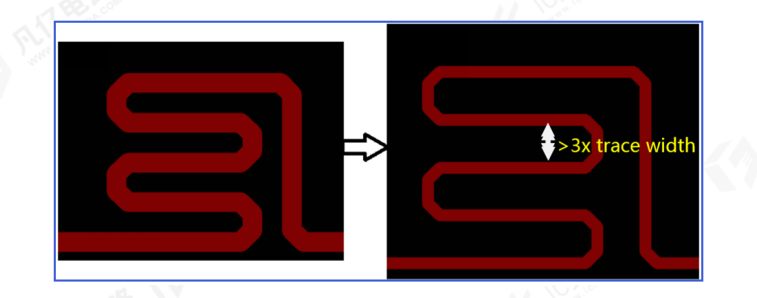
Figure 1 Requirements for Serpentine Routing
- Length matching should be performed in the horizontal or vertical direction as much as possible, and should be avoided on diagonal traces. The length matching processing shall not be too scattered, and should be concentrated as much as possible to ensure aesthetics. In principle, after processing one signal line, the second signal line shall be trimmed first to be adjacent to it, and then the length matching of the second line shall be performed, to ensure space utilization and the overall aesthetics of the design. In the same design, the height of the serpentine length matching shall be controlled to be approximately the same without excessive difference, as shown in Figure 2.
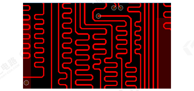
Figure 2 Interlocking Serpentine Length Matching for PCB
- After completing the length matching, inspect the reference plane of the traces, and crossing plane splits is not allowed. Important signals such as clock signals on the PCB (usually ending with clk) shall also avoid crossing plane splits, which will lead to sudden changes in signal impedance, as shown in Figure 3.
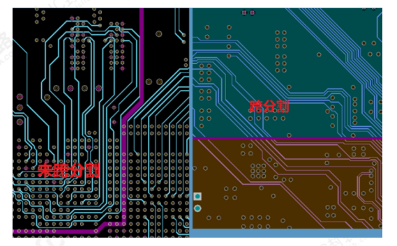
Figure 3 Plane Split Crossing in PCB Routing
- When the reference plane of the trace crosses different power layers, it is recommended to add decoupling capacitors to ground on the two power layers respectively to provide a complete return path, as shown in Figure 4.
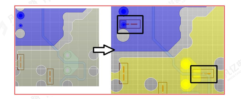
Figure 4 Treatment for Plane Split Crossing of Traces
- For intra-pair length matching of differential signals, the length compensation shall be performed near the position where the decoupling mismatch occurs. The height and width of the intra-pair length matching shall comply with the requirements shown in Figure 5 below.
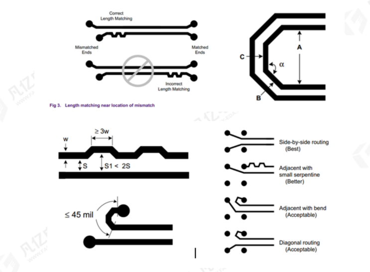
Figure 5 Length Matching Requirements for Differential Traces
About Maxipcb
Maxipcb empowers innovators to turn cutting-edge technologies into reality.
We offer one-stop solutions for design, simulation, testing, PCB manufacturing, component procurement and SMT assembly, enabling efficient development, rapid deployment and risk control across the full product lifecycle.Serving the world in communications, industrial automation, aerospace, automotive, semiconductor and beyond, we build a safer, more connected future together.
