The author has analysed whether a PCB can carry high currents of 100–150A. Let us take a look.
The author has analysed whether a PCB can carry high currents of 100–150A. Let us take a look.
A typical PCB can carry 150A, but in principle, this is not recommended for regular or continuous use. The discussion below focuses on three main aspects:
-
PCB design methods for carrying high currents
-
Important considerations when carrying high currents on a PCB
-
Recommended practices for carrying high currents on a PCB
I. PCB Design Methods for Carrying High Currents
Here are three common PCB design methods for carrying high currents:
-
Increase trace width – The general rule is 1A per 1 mm (40 mil) of trace width.
-
Increase copper thickness – 1 oz, 2 oz, or more.
-
Open the solder mask on the trace and apply additional solder, silver, or copper (solder‑opening with reinforcement).
These are basic operations and will not be repeated in detail here.
II. Important Considerations When Carrying High Currents on a PCB
First, there is a serious issue with heat generation. Even if the above measures (1 and 2) are applied, localised heating is still difficult to manage, because current does not flow uniformly across the conductor. Moreover, copper and tin have significantly different resistivities, so current tends to flow mainly through the copper foil, which can cause severe board heating.
It is important to remember that the glass‑transition temperature (Tg) of commonly used FR‑4 is typically between 140 °C and 170 °C. Exceeding this temperature may not cause the board to catch fire, but it will directly soften the substrate and severely degrade its electrical performance.
Second, the reliability of the board is greatly compromised when using the solder‑opening method, because the additional solder may melt during a fault condition, leading to an open circuit.
III. Recommended Practices for Carrying High Currents on a PCB
First, use busbars or other high‑current conductors, or directly connect copper plates to the high‑current section.
Second, use a multi‑layer board for high‑current transmission. However, thermal simulation is required because current distribution is not uniform and may lead to localised overheating. The analysis should be based on the specific copper thickness and trace width.
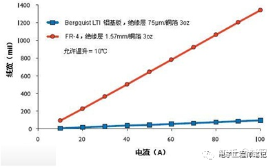
Third, consider aluminium‑based PCBs. Compared with FR‑4, aluminium‑based boards offer much better heat dissipation and higher mechanical strength. However, even with aluminium‑based boards, temperature rise must be carefully considered under a 150A high current. The following figure is provided for reference only: