Route traces according to the 50‑Ω impedance line width, preferably starting from the centre of the pad, keeping traces straight, and routing on the surface layer wherever possible. Use 45° corners or arc routing where turns are necessary, and it is recommended to make turns near capacitors or resistors.
Route traces according to the 50‑Ω impedance line width, preferably starting from the centre of the pad, keeping traces straight, and routing on the surface layer wherever possible. Use 45° corners or arc routing where turns are necessary, and it is recommended to make turns near capacitors or resistors. If device routing matching requirements are specified, strictly follow the reference lengths given in the datasheet – for example, the routing length between an amplifier transistor and a capacitor, or between inductors, etc.
1. General Best Practices
To achieve more reasonable high‑frequency PCB design and better anti‑interference performance, the following aspects should be considered:
(1) Reasonable selection of layer count – In PCB design, using inner planes as power and ground layers provides shielding, effectively reducing parasitic inductance, shortening signal trace lengths, and reducing crosstalk between signals.
(2) Routing style – Traces should be routed with 45° corners or arcs to reduce high‑frequency signal emission and mutual coupling.
(3) Trace length – The shorter the trace, the better; the shorter the parallel run between two traces, the better.
(4) Number of vias – The fewer vias, the better.
(5) Inter‑layer routing direction – Routing directions between adjacent layers should be perpendicular (e.g., top layer horizontal, bottom layer vertical) to reduce signal interference.
(6) Copper pouring – Adding grounded copper pours can reduce signal interference.
(7) Guard traces (trace shielding) – Guarding critical signal lines with ground traces can significantly improve their immunity, and interference sources can also be guarded to prevent them from affecting other signals.
(8) Signal traces – Signal traces must not form loops; they should be routed in a daisy‑chain fashion.
2. Routing Priority
Critical signals first: Small analog signals, high‑speed signals, clock signals, and synchronous signals should be routed first.
Density priority: Start routing from the component with the most complex interconnections on the board, and from the most densely interconnected areas.
Key points:
-
Provide dedicated routing layers for clock signals, high‑frequency signals, and sensitive signals whenever possible, and ensure the smallest possible loop area. Where necessary, use manual priority routing, shielding, and increased clearances to ensure signal quality.
-
The EMC environment between power and ground layers is relatively poor; avoid routing interference‑sensitive signals in these areas.
-
Nets with impedance‑control requirements should be routed according to the specified line length and width.
3. Clock Routing
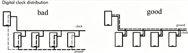
Clock lines are one of the most significant factors affecting EMC. Use as few vias as possible on clock lines, avoid parallel routing with other signal traces, keep them away from general signal lines to prevent interference, and stay clear of power supply areas on the board to avoid mutual interference between power and clock signals.
If the board has a dedicated clock‑generation chip, no traces should be routed beneath it; a copper pour should be placed underneath, and if necessary, a separate ground island may be created. Many ICs have reference crystal oscillators – no traces should be routed beneath these crystals, and copper isolation should be applied.
4. Right‑Angle Corners
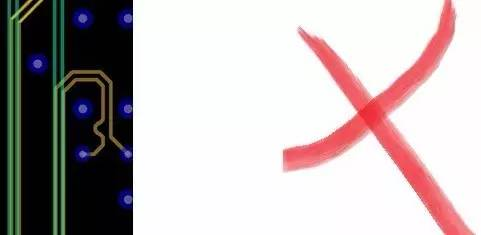
Right‑angle corners are generally avoided in PCB routing and have become a common measure of routing quality. How much impact does a right‑angle corner actually have on signal transmission? In principle, a right‑angle corner changes the trace width, causing impedance discontinuity. In fact, not only right angles, but also obtuse and acute angles can cause impedance variations.
The effects of right‑angle corners on signals are mainly in three aspects:
-
The corner can be modelled as a capacitive load on the transmission line, slowing rise time.
-
Impedance discontinuity causes signal reflection.
-
The sharp tip of the right angle generates EMI.
5. Acute Angles
(1) For high‑frequency currents, when a trace bends at a right or acute angle, the magnetic flux density and electric field strength near the corner are higher, radiating stronger electromagnetic waves. The inductance and inductive reactance at that point are also larger than with obtuse or rounded corners.
(2) For digital bus routing, obtuse or rounded corners occupy less area. With the same trace spacing, the total width occupied by obtuse‑angled bends is about 0.3 times less than with right‑angle bends.

6. Differential Pair Routing
(Refer to: Differential Pair Routing and Impedance Matching)
Differential signals are increasingly used in high‑speed circuit design, and the most critical signals in a circuit often use differential structures. In simple terms, the driver sends two equal‑amplitude, opposite‑phase signals, and the receiver determines the logic state ("0" or "1") by comparing the voltage difference between them. The pair of traces carrying the differential signal is called a differential pair.
Compared with ordinary single‑ended signal traces, differential signals offer three major advantages:
a. Strong noise immunity – Because the two differential traces are tightly coupled, external noise is coupled to both lines almost simultaneously. Since the receiver only cares about the difference between the two signals, common‑mode noise can be completely cancelled.
b. Effective EMI suppression – For the same reason, because the two signals have opposite polarities, their radiated electromagnetic fields cancel each other. The tighter the coupling, the less electromagnetic energy leaks to the outside.
c. Precise timing positioning – The switching of a differential signal occurs at the crossing point of the two signals, unlike single‑ended signals that rely on high and low threshold voltages. This makes it less affected by process and temperature variations, reduces timing errors, and is more suitable for low‑amplitude signal circuits. The popular LVDS (Low Voltage Differential Signaling) technology is based on this small‑amplitude differential signal approach.
For PCB engineers, the key concern is how to ensure that these advantages are fully realised in actual routing. Anyone with layout experience knows the general requirements for differential routing: "equal length and equal spacing." Equal length ensures that the two differential signals maintain opposite polarities at all times, reducing common‑mode components. Equal spacing mainly ensures consistent differential impedance and minimises reflections. The "keep them as close as possible" principle is also sometimes a requirement.
7. Serpentine Routing
Serpentine routing is a common trace pattern used in layout, primarily to adjust signal delay and meet system timing requirements. Designers should be aware that serpentine traces can degrade signal quality and alter propagation delay, so they should be avoided where possible. However, in practice, to ensure adequate hold time or reduce timing skew within a group of signals, deliberate detour routing is often unavoidable.
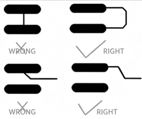
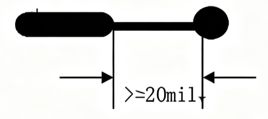
Key points: Differential signal pairs should be routed in parallel, with as few vias as possible. If vias are necessary, both lines should be routed through vias together to maintain impedance matching. A group of buses with the same attributes should be routed in parallel and length‑matched as much as possible. Vias leading from SMD pads should be placed as far away from the pads as practical.
9. Power and Ground Handling
Even if the overall PCB routing is well done, inadequate consideration of power and ground can cause interference, degrading product performance and sometimes even affecting product success. Therefore, power and ground routing must be taken seriously to minimise noise interference and ensure product quality.
Every engineer working on electronic product design understands the causes of noise between ground and power lines. Here are some methods to reduce or suppress that noise:
(1) Add decoupling capacitors between power and ground – this is well known.
(2) Make power and ground traces as wide as possible. Ideally, the ground trace should be wider than the power trace, with the priority: ground > power > signal. Typical signal trace widths are 0.2‑0.3 mm, with a minimum of 0.05‑0.07 mm; power traces are 1.2‑2.5 mm. For digital PCBs, a wide ground conductor can form a loop, creating a ground grid (but this should not be used for analogue ground).
(3) Use large copper areas as ground planes – connect all unused areas on the board to ground. Alternatively, use a multi‑layer board with dedicated layers for power and ground.
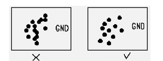
In areas with dense vias, avoid creating interconnected voids in the power and ground planes that could split the plane and increase the return‑path area for signal traces.
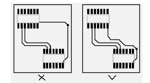
Ground loop rule:
The loop area formed by a signal trace and its return path should be as small as possible. The smaller the loop area, the less radiation and the less susceptibility to external interference.
Device decoupling rules:
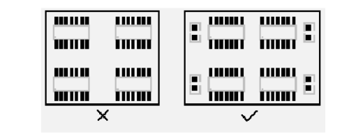
A. Add necessary decoupling capacitors on the PCB to filter interference on the power supply and stabilise the power signal. In multi‑layer boards, the placement of decoupling capacitors is generally less critical, but in double‑layer boards, capacitor placement and power routing directly affect system stability – sometimes even determining design success or failure.
B. In double‑layer board design, current should generally pass through the filter capacitor before reaching the device.
C. In high‑speed circuit design, correct use of decoupling capacitors is critical to overall board stability.
10. Common Grounding for Digital and Analog Circuits
Many PCBs today are not single‑function (digital or analog) but mixed‑signal boards. Therefore, routing must consider mutual interference, especially ground noise.
Digital circuits operate at high frequencies, while analog circuits are highly sensitive. For signal traces, high‑frequency signals should be kept as far as possible from sensitive analog components. For grounding, the entire PCB has only one external connection point, so the digital and analog grounds must be handled internally. Within the board, digital and analog grounds are actually separate and not connected to each other – they are connected only at the interface to the outside world (e.g., connectors). There should be only one shorting point between digital and analog grounds. Some designs may not connect them at all on the PCB, depending on system design.
11. Routing Signals on Power or Ground Layers
In multi‑layer PCB routing, if only a few traces remain un‑routed on the signal layers, adding extra layers would be wasteful and increase cost. To solve this, consider routing on the power or ground layers. The power layer should be used first, followed by the ground layer, because it is best to preserve the integrity of the ground plane.
12. Handling Connections in Large Copper Areas
In large ground (or power) copper areas, component leads are often connected to them. This requires careful consideration. For electrical performance, a full connection between the pad and the copper area is preferred. However, for soldering and assembly, this can cause problems:
① Higher power heating is required for soldering.
② Increased risk of cold solder joints.
To balance electrical performance and manufacturability, use a cross‑shaped (spoke) pad connection, known as a thermal pad (or thermal relief). This significantly reduces the risk of cold solder joints caused by excessive heat sinking during soldering. The same approach applies to power and ground layer connections in multi‑layer boards.
13. Role of the Grid System in Routing
In many CAD systems, routing is determined by the grid system. If the grid is too fine, although more routing paths are available, the step size is too small, and the data volume becomes large, requiring greater storage capacity and affecting the processing speed of computer‑based electronic products. Some paths may be invalid – blocked by component pads, mounting holes, or locating holes. If the grid is too coarse, there are too few paths, reducing routing completion rates. Therefore, a grid system with reasonable density is essential.
The standard spacing between component leads is 0.1 inch (2.54 mm), so the grid base is typically set to 0.1 inch (2.54 mm) or sub‑multiples such as 0.05 inch, 0.025 inch, 0.02 inch, etc.
14. Design Rule Check (DRC)
After routing is complete, carefully check whether the design complies with the defined rules, and also confirm that the rules meet PCB manufacturing requirements. Typical checks include:
(1) Clearances between traces, traces and pads, traces and vias, pads and vias, and between vias – are they reasonable and within manufacturing capabilities?
(2) Are power and ground trace widths appropriate? Is there tight coupling between power and ground (low wave impedance)? Are there any areas where the ground could be widened?
(3) Have critical signals received the best treatment – shortest length, guard traces, clear separation of input and output lines?
(4) Do the analog and digital sections have independent ground returns?
(5) Could any later‑added graphics (such as logos or labels) cause signal shorts?
(6) Modify any non‑ideal trace shapes.
(7) Are fabrication/test coupons included? Does the solder mask meet production requirements? Are solder‑mask dimensions appropriate? Is silkscreen overlapping component pads, which could affect assembly quality?
(8) On multi‑layer boards, are the power and ground plane edges recessed? Exposed copper on the board edge could cause shorts.
15. Check the 3W and 3H Principles
To reduce crosstalk between traces, ensure sufficient trace spacing. When the centre‑to‑centre spacing is at least 3 times the trace width, 70 % of the electric field is contained – this is the 3W rule. To achieve 98 % containment, use 10W spacing.
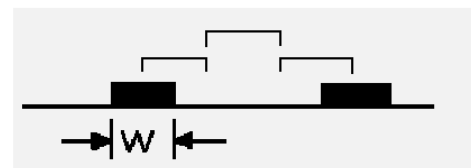
(1) Clock, reset, signals above 100 MHz, and critical bus signals must satisfy the 3W principle with respect to other signals. There should be no long parallel runs on the same or adjacent layers, and vias on the link should be minimised.
(2) Regarding the number of vias for high‑speed signals, some device guidelines may be strict. The interconnect design principle is that, apart from necessary pin‑fanout vias, no extra vias should be placed on inner layers. They have routed 8 G PCIe 3.0 traces with up to 4 vias without issues.
(3) The centre‑to‑centre spacing of clocks and high‑speed signals on the same layer must strictly satisfy the 3H rule (where H is the distance from the signal layer to the reference plane). Signals on adjacent layers must not overlap; it is also recommended to satisfy the 3H principle. Dedicated tools can check for crosstalk issues.
The main purpose is to prevent interference between modules operating at different frequencies, while also minimising the routing length in the high‑frequency section. For mixed‑signal circuits, analog and digital sections may be placed on opposite sides of the board, routed on different layers, and separated by a ground plane.
About Maxipcb
Maxipcb empowers innovators to turn cutting-edge technologies into reality.We offer one-stop solutions for design, simulation, testing, PCB manufacturing, component procurement and SMT assembly, enabling efficient development, rapid deployment and risk control across the full product lifecycle.
Serving the world in communications, industrial automation, aerospace, automotive, semiconductor and beyond, we build a safer, more connected future together.

