When high‑frequency/microwave RF signals are fed into a PCB circuit, the circuit inevitably generates a certain amount of heat due to losses inherent in the circuit itself and the circuit material. The greater the loss, the higher the power passing through the PCB material, and the more heat will be generated. When the circuit's operating temperature exceeds its rated value, the circuit may suffer from various problems.
When high‑frequency/microwave RF signals are fed into a PCB circuit, the circuit inevitably generates a certain amount of heat due to losses inherent in the circuit itself and the circuit material. The greater the loss, the higher the power passing through the PCB material, and the more heat will be generated. When the circuit's operating temperature exceeds its rated value, the circuit may suffer from various problems. For example, the well‑known typical operating parameter for PCBs is MOT (Maximum Operating Temperature). When the operating temperature exceeds the MOT, the performance and reliability of the PCB circuit are threatened. By combining electromagnetic modelling and experimental measurement, understanding the thermal characteristics of RF/microwave PCBs helps to avoid performance degradation and reduced reliability caused by high temperatures.
Understanding how insertion loss arises in circuit materials helps to better describe the important factors related to the thermal performance of high‑frequency PCB circuits. This article uses a microstrip transmission line circuit as an example to discuss the trade‑offs associated with circuit thermal performance. In a double‑sided PCB microstrip circuit, losses include dielectric loss, conductor loss, radiation loss, and leakage loss. The magnitudes of these loss components vary significantly. With few exceptions, leakage loss in high‑frequency PCB circuits is generally very low. In this article, because leakage loss values are very low, they are ignored for the present discussion.
Radiation Loss
Radiation loss depends on many circuit parameters, including operating frequency, substrate thickness, PCB dielectric constant (relative permittivity or εr), and the design topology. In terms of design, radiation loss often arises from poor impedance transitions in the circuit or from discontinuities in electromagnetic wave propagation. Circuit impedance transition regions typically include signal launch areas, stepped‑impedance points, stubs, and matching networks. Proper circuit design can achieve smooth impedance transitions, thereby reducing radiation loss. Of course, it should be recognised that impedance mismatch at any circuit interface can cause radiation loss. From the perspective of operating frequency, radiation loss generally increases with frequency.
The circuit material parameters most relevant to radiation loss are the dielectric constant and the thickness of the PCB material. Thicker substrates tend to cause more radiation loss, and lower εr materials result in higher radiation loss. By making appropriate trade‑offs, using a thinner substrate can be a way to compensate for radiation loss caused by low‑εr materials. The influence of substrate thickness and εr on radiation loss is frequency‑dependent. When the substrate thickness does not exceed 20 mil and the operating frequency is below 20 GHz, radiation loss is very low. Since most of the circuit modelling and measurements in this article are below 20 GHz, the discussion here will ignore the effect of radiation loss on circuit heating.
After ignoring radiation loss below 20 GHz, the insertion loss of the microstrip transmission line circuit mainly consists of dielectric loss and conductor loss. The proportion of these two components depends largely on the substrate thickness. For thinner substrates, conductor loss dominates. For many reasons, conductor loss is generally difficult to predict accurately. For example, the surface roughness of the conductor has a significant effect on electromagnetic wave transmission characteristics. The surface roughness of copper foil not only changes the propagation constant of electromagnetic waves in the microstrip circuit but also increases conductor loss. Due to the skin effect, the influence of copper foil roughness on conductor loss is also frequency‑dependent. Figure 1 compares the insertion loss of 50 Ω microstrip transmission line circuits based on PCB substrate thicknesses of 6.6 mil and 10 mil.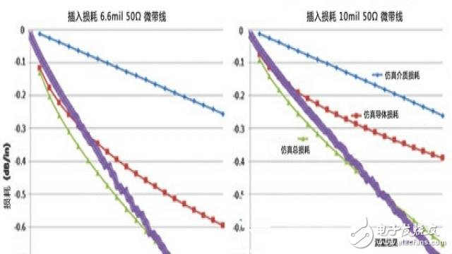
Figure 1. Comparison of 50 Ω microstrip transmission line circuits based on different PCB thicknesses – measured and simulated results
The curves in Figure 1 include both measured and simulated results. The simulated results were obtained using Rogers' MWI‑2010 microwave impedance calculation software, which applies analytical equations from classic papers in the field of microstrip modelling. The measured data in Figure 1 were obtained using a differential‑length measurement method with a vector network analyser. It can be seen that the simulated total loss curves are basically consistent with the measured results. The figure also shows that for the thinner circuit (left curve, 6.6 mil thickness), conductor loss is the dominant component of the total insertion loss. As the circuit thickness increases (right curve, 10 mil thickness), dielectric loss and conductor loss become closer to each other, both contributing to the total insertion loss.
The circuit material parameters used in the simulation models and actual circuits in Figure 1 are: dielectric constant 3.66, loss tangent 0.0037, and copper surface roughness 2.8 µm RMS. When the copper surface roughness of the same circuit material is reduced, the conductor losses for the 6.6 mil and 10 mil circuits in Figure 1 would decrease significantly; the effect for the 20 mil circuit is less pronounced. Figure 2 shows measured results for two circuit materials with different roughness levels: Rogers RO4350B™ standard material (high roughness) and Rogers RO4350B LoPro™ material (low roughness).
Figure 2 clearly shows the advantage of using substrates with smooth copper foil for microstrip circuits. For thinner substrates, using smooth copper foil can significantly reduce insertion loss. For a 6.6 mil substrate, insertion loss at 20 GHz is reduced by 0.3 dB; for a 10 mil substrate, by 0.22 dB; and for a 20 mil substrate, by only 0.11 dB.
As shown in Figures 1 and 2, the thinner the substrate, the higher the insertion loss. This means that when a certain RF/microwave power is fed into the circuit, the thinner circuit will generate more heat. When considering the thermal trade‑off, a thinner circuit produces more heat at high power levels compared to a thicker circuit, but on the other hand, a thinner circuit can maintain a relatively lower temperature because it has a shorter heat flow path to a heatsink.
To address circuit heating issues, an ideal thin circuit should have the following characteristics: low loss tangent, smooth copper surface, low εr, and high thermal conductivity. Compared to high‑εr materials, low‑εr materials allow wider conductor widths for the same impedance, which helps reduce conductor loss. From the perspective of heat dissipation, although most high‑frequency PCB substrates are very poor thermal conductors compared to copper, the thermal conductivity of the circuit material remains a very important parameter.
A large amount of discussion on the thermal conductivity of circuit substrates has been presented in earlier articles, and this article will reference some of those results and information. For example, the following equation and Figure 3 help to understand the factors affecting the thermal performance of PCB circuit materials. In the equation, k is thermal conductivity (W/m/K), A is area, TH is the hot‑source temperature, TC is the cold‑source temperature, and L is the distance between the hot and cold sources.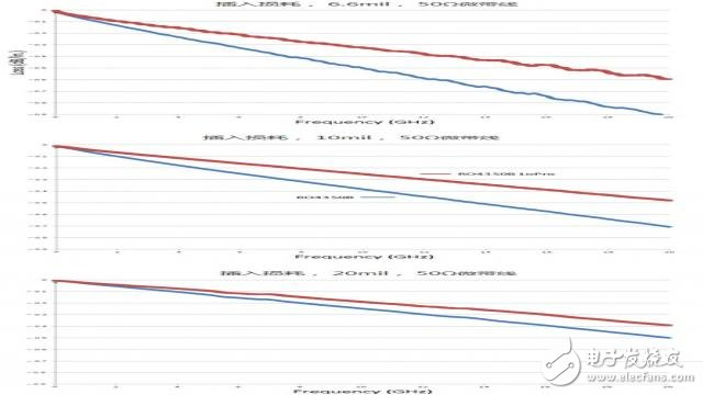
Figure 2. Comparison of microstrip transmission line loss based on different dielectric layer thicknesses and copper conductor roughness
Thermal Model
Figure 3 and its associated equation represent a simple thermal model of a microstrip circuit. In a microstrip circuit, the top conductor layer serves as the signal plane, the bottom conductor layer as the ground plane, and the dielectric layer is between them. In the thermal model of Figure 3, the signal plane is assumed to be the heat source, with heat generated in that plane; the ground plane is assumed to be the cold source with a heatsink, and the substrate acts as the thermal conductor transferring heat from the signal plane to the ground plane. Although the actual heat generation process in a microstrip circuit is complex, this assumption is acceptable for a simple thermal model. In practice, the circuit substrate is a very poor thermal conductor. For example, copper, as a good thermal conductor, has a thermal conductivity of 400 W/m/K, while most commercial PCB substrates have much lower thermal conductivity – only 0.2 to 0.3 W/m/K.
The heat flow equation explains why thinner circuits (smaller L) improve heat flow and provide better heat dissipation at high power levels. At the same time, at high power levels, substrates with higher thermal conductivity allow greater heat flow and better heat dissipation compared to low‑thermal‑conductivity substrates.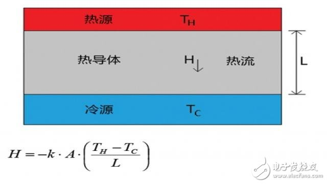
Figure 3. Basic thermal model of a microstrip transmission line circuit, where the signal plane is the heat source and the ground plane with heatsink is the cold source
The power limit of a high‑frequency PCB circuit depends on the temperature reached due to heating at that power level. PCB materials also have a Relative Thermal Index (RTI) obtained through UL safety certification, which is the maximum temperature at which the material can operate for a specified time without degrading key PCB properties. When the substrate is fabricated into an actual circuit, other factors must also be considered from the thermal management perspective. For example, the circuit can also be evaluated for MOT, which measures the maximum temperature at which the circuit material can operate for a specified time without degrading key properties. For the same PCB material, the MOT value is always lower than the RTI value.
The RF/microwave power handling of a PCB is limited by the circuit's MOT and the operating environment. If the power level causes heating that does not exceed the MOT, that power level is acceptable. Of course, the applied power will cause heating that raises the circuit temperature above the ambient temperature. When the ambient temperature is +25 °C, the heat generated by the applied RF/microwave power will not exceed the MOT. However, if the ambient temperature is +50 °C and the same power level is applied, the heat generated may exceed the MOT and cause problems. As analysed above, the power‑handling capability of high‑frequency PCB circuits depends, to some extent, on the external operating environment.
Influencing Factors
To better understand the factors affecting the thermal performance of PCB circuits, 50 Ω microstrip transmission line circuits similar to those in Figures 1 and 2 were used for investigation. Circuits of different thicknesses and different copper roughnesses were fabricated on the same type of PCB material. In addition to fabricating circuits on low‑loss PCB materials, circuits were also fabricated on high‑loss materials for evaluation. The input RF/microwave power ranged from 5 W to 85 W. All circuits had return loss better than 18 dB at 3.4 GHz and used a 0.25‑inch thick copper cover plate as the heatsink. The circuits were attached to the heatsink using COOLSPAN® thermally conductive adhesive film, a thermosetting adhesive material with a thermal conductivity of 6 W/m/K.
An infrared thermal imager was used to record the temperature rise of the circuits under certain power conditions. To ensure measurement accuracy, the circuit and its surface colour within the field of view of the thermal imager should be uniform. A black paint was applied to the surface to allow the thermal imager to obtain accurate thermal images. However, the black paint increases the insertion loss of the transmission line. The increased insertion loss means that the recorded heat is higher, which can be considered as the worst‑case heat generation. In addition, since the ground‑signal‑ground area of the coplanar waveguide was coated with black paint and the current density in that region is relatively high, the effect on insertion loss (temperature rise) of the grounded coplanar waveguide is greater than that for microstrip circuits.
Table 1 shows the circuit structures, material types and properties, insertion losses, and temperature rise results for different circuits. The table provides a wealth of information for comparing the thermal effects of different circuit materials. For example, it allows comparison of circuits on the same substrate with different copper roughness: Circuit 3 uses rough copper foil, and Circuit 4 uses smooth copper foil. As expected, the circuit with smooth copper foil has lower insertion loss than the one with rough copper foil, and therefore Circuit 4 shows a smaller temperature rise.
Table 1. Temperature rise of circuits based on different structures and materials under the same power conditions
Comparing Circuit 1 and Circuit 3 shows that changing the PCB material thickness results in different temperature rises. These two circuits are identical except for PCB thickness – the same material type and copper roughness. Circuit 1 is thinner than Circuit 3 and has higher insertion loss. As previously discussed, when sufficient RF/microwave power is applied, higher insertion loss generates more heat. However, as shown in Table 1, the thinner Circuit 1 actually has a lower temperature rise than the thicker Circuit 3. This is because Circuit 1 has a shorter heat‑flow path L, as illustrated in Figure 3.
Comparing Circuit 1 and Circuit 2, the materials used are identical, but the circuit designs differ. Circuit 2 is a coplanar waveguide (CPW) circuit, tightly coupled, with plated through‑holes (PTHs) near the edges of the coplanar ground‑signal‑ground lines. A comparison of the microstrip and CPW structures is shown in Figure 4.
Insertion Loss
The tightly coupled CPW circuit offers better heat dissipation than the microstrip circuit. In Circuit 2, the centre signal conductor and adjacent ground conductors of the CPW have a gap of 5 mil, and there is a row of ground vias along the edges of the ground conductors. These vias are copper‑plated and act as thermal conduction paths, effectively transferring heat from the signal plane to the ground plane. As shown in Table 1, the difference in insertion loss between the microstrip circuit (Circuit 1) and the grounded CPW circuit (Circuit 2) is very pronounced. Since both circuits are fabricated on materials of the same thickness, higher insertion loss means more heat generated. Although the grounded CPW circuit generates more heat than the microstrip circuit, the heat‑dissipating effect of the grounded vias results in temperature rises that are not significantly different.
Figure 4. Transmission line circuits used for PCB thermal studies: (a) microstrip structure; (b) grounded coplanar waveguide structure corresponding to Circuit 2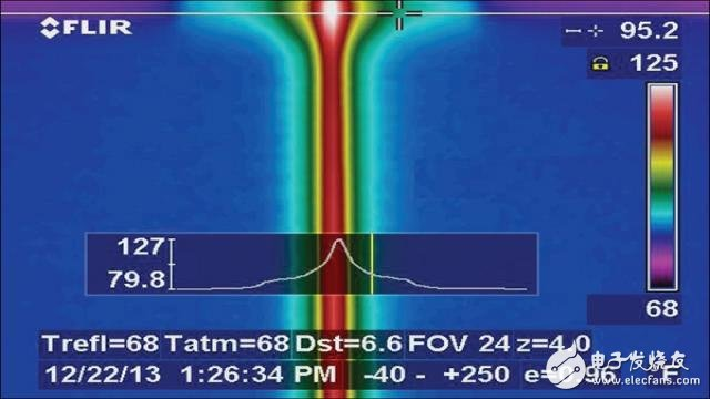
Figure 5. Top‑view thermal image of the microstrip transmission line; the hot spot corresponds to the signal launch area
Finally, comparing Circuit 3 and Circuit 5 in Table 1 shows that, apart from both having a PCB thickness of 20 mil, many other parameters differ. Circuit 5 is based on low‑cost FR‑4 material, which is rarely used at microwave frequencies. Circuit 5 has much higher insertion loss than Circuit 3. In addition, Circuit 5 also has many disadvantages in thermal performance, including high loss tangent, low thermal conductivity, and high εr. For a 50 Ω transmission line, high εr means narrower line widths, which, compared to the low‑εr Circuit 3, results in higher conductor loss.
For any circuit heating study, the signal launch area is typically a critical point because one always wants the RF power to be transferred as efficiently as possible from the input connector into the circuit under test. In this study, all experiments used high‑performance 3.5 mm end‑launch connectors from Southwest Microwave. Although the circuits are optimised for good signal launch, there is always some energy loss in the launch region, which causes higher heating there. Because the launch connector is a good thermal conductor, some heat is conducted through the connector to the heatsink. Under high‑power conditions, as shown in thermal images, the temperature in the signal launch area is higher than that in the main body of the microstrip circuit. Figure 5 shows a thermal image for such a case; this circuit is not listed in Table 1.
Figure 5 is a thermal image of a 12‑mil thick 50 Ω microstrip transmission line circuit. The insertion loss of this circuit after applying black paint was 0.23 dB/in. The maximum temperature in the signal launch area was +127 °F, while the maximum temperature in the main body of the circuit was +119 °F. Because the signal launch area has more heatsink contact than the main body, the temperature difference between the two measured points is not large, but it is still worth noting.
Conclusion
This article has analysed the different components of insertion loss, a simple thermal model, and some key circuit material parameters from the perspective of thermal management, to help understand the thermal effects of high‑power RF/microwave signals in PCB circuits. In general, relatively thin circuit materials, high thermal conductivity, smooth copper surfaces, and low loss tangent all help to reduce the thermal effects of high‑power RF/microwave signals in PCB circuits.
About Maxipcb
Maxipcb empowers innovators to turn cutting-edge technologies into reality.We offer one-stop solutions for design, simulation, testing, PCB manufacturing, component procurement and SMT assembly, enabling efficient development, rapid deployment and risk control across the full product lifecycle.
Serving the world in communications, industrial automation, aerospace, automotive, semiconductor and beyond, we build a safer, more connected future together.
