A friend of mine is facing the second round of layoffs at his company this year, and unfortunately, he’s on the list. He’s been polishing his resume and preparing for interviews these days. Coincidentally, he asked me a few questions last Sunday—they’re quite insightful, so I’ll pick one to discuss with everyone.
A friend of mine is facing the second round of layoffs at his company this year, and unfortunately, he’s on the list. He’s been polishing his resume and preparing for interviews these days. Coincidentally, he asked me a few questions last Sunday—they’re quite insightful, so I’ll pick one to discuss with everyone.
An Interview Question…
Let’s start with the question: What is the conducted emission path of common-mode noise in a Buck converter?
This question seems simple but actually tests deep technical expertise. It contains three key terms: Buck, common-mode noise, and conducted emission. Therefore, the interviewee needs to clarify:
① The topological structure of the Buck converter (we’ve discussed this extensively before—longtime followers are certainly familiar with it, so I won’t repeat it);
② The difference between common-mode noise and differential-mode noise (if you can’t tell them apart, there’s no point in further discussion);
③ Where do common-mode noise and differential-mode noise originate? (If you don’t know the source, how can you understand the path?);
④ What is the conducted emission path of common-mode noise? (Note: This refers to conducted, not radiated, emission.)
I think explaining these extended questions is challenging. It tests one’s understanding of Buck converters, differential/common-mode noise, EMI principles, and related knowledge. This question is suitable for interviewing senior hardware development engineers with 4–5 years of experience.
Naturally, the question is highly targeted—it limits our scope, so we don’t need to consider differential-mode noise or radiated emission, which would double the difficulty.
Below, we’ll analyze the four refined questions one by one.
1. Topological Structure of the Buck Converter
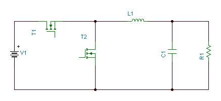
Topological structure diagram of the Buck converter (labeled with L1, T2, R1)
As shown in the figure above, the topological structure of the Buck converter won’t be elaborated on here. I believe students who have followed "Hardware Micro-Lecture" for a long time are very familiar with it—after all, we’ve discussed many issues based on Buck converters. Newcomers can learn on their own from "40 Original Technical Articles—Free to Take!".
2. Common-Mode Noise and Differential-Mode Noise
From an EMI perspective, noise is divided into two categories: common-mode noise and differential-mode noise.
There are countless explanations of differential and common-mode signals online. Here, I’ll only share my own understanding:
- Differential-mode signals: Signals relative to the negative pole of the transmission line loop; signal return paths all flow back to the negative pole of the signal source through the transmission line.
- Common-mode signals: Signals relative to Earth GND; signal return paths all flow back to Earth GND in the form of displacement current through stray capacitances (such as parasitic capacitances and distributed capacitances).
(The above is a personal understanding, not an official definition—it’s not very rigorous and is for comprehension and reference only.)
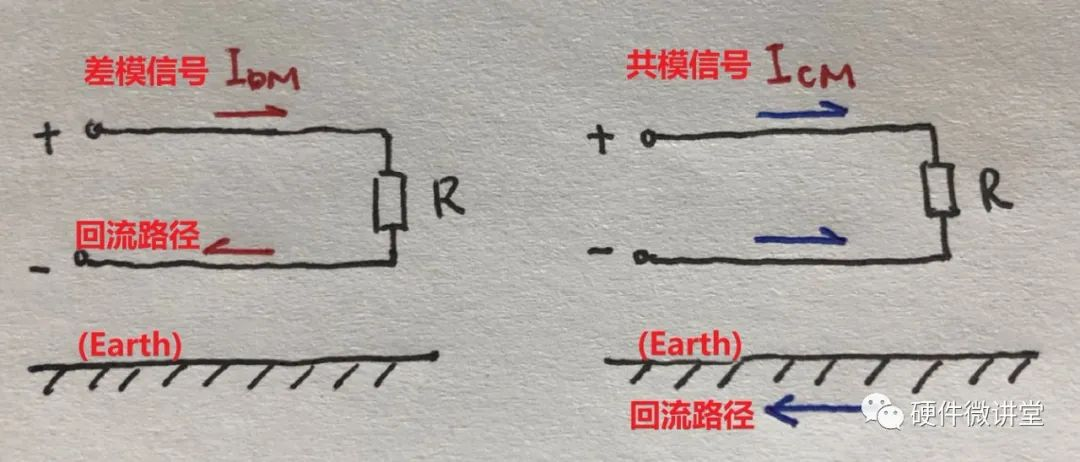
Left: Differential-mode signal (IpM) with visible physical return path; Right: Common-mode signal (IcM) with invisible return path
As shown in the figure, differential-mode signals are easy to understand—their physical loops are visible and tangible. In contrast, common-mode signals are more troublesome: their return paths are invisible, intangible, and hard to trace.
Three key terms are involved in describing common-mode signals: stray capacitance, displacement current, and Earth GND.
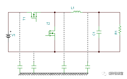
Diagram showing stray capacitances (parasitic capacitances of components, distributed capacitances of PCB traces, and capacitance between the negative pole of the signal loop and Earth GND)
First, stray capacitance: As shown in the figure, components have inherent parasitic capacitances, PCB traces have distributed capacitances, and even the negative pole of the signal loop has capacitance relative to Earth GND. These all serve as return paths for common-mode signals—critical yet invisible paths.
Second, displacement current: The online definition—"the integral of the time rate of change of the electric displacement vector over a surface"—is too obscure! Popularly speaking, it refers to the rate of change of the electric field. Unlike "conduction current," it is not formed by the directional movement of charges, but it induces a changing magnetic field, and this magnetic field is equivalent to that induced by conduction current. Displacement current does not produce thermal or chemical effects, but it does cause magnetic field changes—fascinating!
The aforementioned conduction current is formed by the movement of charges in a conductor (e.g., the directional movement of free electrons)—this is the "current" we commonly refer to. Note the distinction from displacement current.
Third, Earth GND: This is the physical ground (earth), which should be distinguished from the GND that provides the signal current return path. GND is the negative pole of the power loop and a selected reference potential, but it is not a true zero potential. In hardware testing, there is a test called "ground offset," where a certain voltage level is superimposed on GND to raise the reference potential of the entire electrical system, testing whether the system can still operate stably. A true zero potential should be Earth GND.
Everything discussed above about common-mode and differential-mode signals applies equally to "noise." From a physical perspective, common-mode noise and differential-mode noise are also electrical signals—they are just unwanted, undesirable signals that we need to suppress as much as possible.
Frankly speaking, we can only suppress them as much as possible. It is impossible—absolutely impossible—to completely eliminate differential and common-mode noise! Learning to coexist with them harmoniously is a skill.
3. Generation of Common-Mode Noise and Differential-Mode Noise
In the previous section, we distinguished between common-mode and differential-mode based on return paths. But where do these noises originate, and how are they generated?
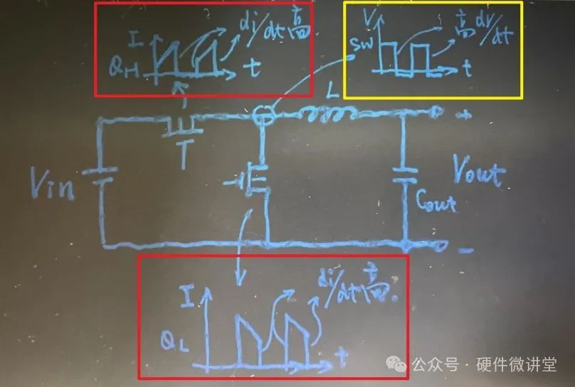
Buck converter waveform diagram (red boxes show current waveforms of two current loops; yellow box shows voltage waveform of the SW node)
Students familiar with the working principle of Buck power supplies know that there are two current loops (as introduced in "Pure Dry Goods! Derivation of DC-DC Inductor Calculation Formula!"). As shown in the two red boxes in the figure, the waveforms of these two current loops are periodic trapezoids, both with steep current changes (high di/dt) that contain many high-order harmonics—this is the source of differential-mode noise. Typically, differential-mode noise is a "current-driven" noise.
Similarly, as shown in the yellow box, the voltage waveform at the SW node (left side of inductor L) is a periodic rectangle with steep voltage changes (high dV/dt) that contain many high-order harmonics—this is the source of common-mode noise. Typically, common-mode noise is a "voltage-driven" noise.
Here are two thinking questions for you:
① Will the di/dt of the MOSFET generate common-mode noise?
② Will the dV/dt of the SW node generate differential-mode noise?
By the way, these two questions are not simple—think about them carefully!
About Maxipcb
Maxipcb empowers innovators to turn cutting-edge technologies into reality.
We offer one-stop solutions for design, simulation, testing, PCB manufacturing, component procurement and SMT assembly, enabling efficient development, rapid deployment and risk control across the full product lifecycle.Serving the world in communications, industrial automation, aerospace, automotive, semiconductor and beyond, we build a safer, more connected future together.


