The packaged and tested chips are theoretically ready for use. However, in real life, an integrated circuit product usually needs many chips to be assembled on a printed circuit board (PCB) to achieve complex functions. One or more integrated circuit chips, together with other components and connectors, are mounted on the printed circuit board and connected by thin copper tape to meet the application requirements.
The packaged and tested chips are theoretically ready for use. However, in real life, an integrated circuit product usually needs many chips to be assembled on a printed circuit board (PCB) to achieve complex functions. One or more integrated circuit chips, together with other components and connectors, are mounted on the printed circuit board and connected by thin copper tape to meet the application requirements. A very common application scenario of printed circuit board is as the motherboard of computers and mobile phones.
Figure 1 shows the internal structure of a mobile phone, from which it can be clearly seen that several chips are assembled on the printed circuit board that constitutes the core motherboard of the mobile phone. These chips not only have their own specific functions, but also can transmit information to each other. The process of mounting the chip to the printed circuit board is called the printed circuit board assembly process. The copper wire on the bare board is called a trace, which is used to connect the connector with the chip assembly. Routes transmit signals between different functional components, so that the printed circuit board can operate in a pre-designed way, and the complexity of these functions is different.
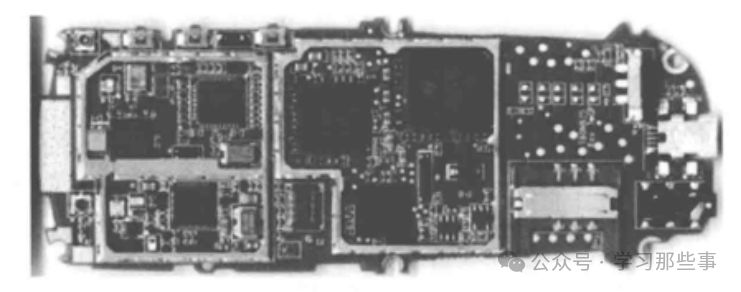
Figure 1: Printed Circuit Board
So, how are these assembled printed circuit boards made? The assembly of printed circuit board is actually a process consisting of several automatic and manual steps. At every step of the process, circuit board manufacturers have two options: manual and automatic. In order to give readers a comprehensive and in-depth understanding of the PCB assembly process, each step will be explained in detail below.
Structure and types of printed circuit boardsThe assembly process of printed circuit board begins with the most basic unit of printed circuit board-substrate. The substrate is composed of four layers of materials, and each layer plays a key role in the functional realization of the final printed circuit board.
1. The composition of the base layerSubstrate: this is the basic material of printed circuit board, which gives it rigidity.
Copper: A thin layer of conductive copper foil will be added to each functional surface of the printed circuit board. If it is a single-sided printed circuit board, the copper foil is on one side; If it is a double-sided printed circuit board, the copper foil is distributed on both sides, which is the copper wiring layer.
Solder resist: Above the copper layer is solder resist, which gives each printed circuit board an iconic green appearance. The role of solder mask is to isolate copper traces from conductive materials and prevent short circuit. In other words, the solder relies on the solder resist to fix all components in corresponding positions. The hole in the solder mask is used to connect the assembly to the circuit board through solder, which is the key link for the smooth assembly process of the printed circuit board, because it can avoid welding on unnecessary parts and effectively prevent short circuit.
Screen printing: White screen printing is the last layer on the printed circuit board. This layer adds signs on the printed circuit board in the form of characters and symbols to remind the functions of each component on the printed circuit board.
2. Types of printed circuit boardsRigid printed circuit board: the most common type of printed circuit board substrate is rigid substrate, which accounts for a high proportion in the assembly process of printed circuit board. The solid core of rigid printed circuit board endows the circuit board with rigidity and thickness. This kind of hard-to-bend printed circuit board base is made of many different materials. Among them, glass fiber is the most common, and its code name is "FR4" (code name of fire-resistant material grade). The cheaper printed circuit board is made of epoxy resin or phenolic resin, but its durability is not as good as FR4.
Flexible printed circuit board: Compared with rigid printed circuit board, flexible printed circuit board has higher flexibility. The material of this kind of printed circuit board is usually flexible high-temperature plastic, such as Kapton polyimide.
Metal core printed circuit board: This kind of circuit board is another alternative to the typical FR4 board. They are made of metal cores. Compared with other circuit boards, they have better heat dissipation performance, which helps to dissipate heat and protect circuit board components that are more sensitive to heat.
About Maxipcb
Maxipcb empowers innovators to turn cutting-edge technologies into reality.
We offer one-stop solutions for design, simulation, testing, PCB manufacturing, component procurement and SMT assembly, enabling efficient development, rapid deployment and risk control across the full product lifecycle.
Serving the world in communications, industrial automation, aerospace, automotive, semiconductor and beyond, we build a safer, more connected future together.

