Based on the developed circuit schematic, simulation can be performed and PCB design can be implemented by exporting Gerber/drill files. No matter what the design is, engineers need to have an accurate understanding of how the circuits (and electronic components) should be laid out and how they operate.
Based on the developed circuit schematic, simulation can be performed and PCB design can be implemented by exporting Gerber/drill files. No matter what the design is, engineers need to have an accurate understanding of how the circuits (and electronic components) should be laid out and how they operate. For electronic engineers, finding the right PCB design software tool can be a challenging task. A software tool suitable for one PCB project may not be well-suited for other projects. Engineers expect circuit board design tools to be intuitive, equipped with useful functions, stable enough to mitigate risks, and come with a robust component library that makes it applicable to multiple projects.
Hardware Issues
For IoT projects, integration is critical to performance and reliability. The integration of conductive and non-conductive materials in PCBs requires IoT designers to study the interaction between various electrical and mechanical aspects of the design. In particular, as component sizes continue to shrink, electrical heating on the PCB becomes increasingly critical. At the same time, functional requirements are also continuously rising. To achieve the performance-based design objectives, temperature response, the behavior of electrical components on the circuit board, and overall thermal management are critical to the function and reliability of the system.
PCBs must be isolated to ensure protection, preventing short circuits by protecting the copper traces placed on the board to build the electronic system. Compared with low-cost alternatives such as Synthetic Resin Bonded Paper (SRBP, FR-1, FR-2), FR-4 is more suitable as a substrate material due to its superior physical and mechanical properties, especially its ability to retain data at high frequencies, high heat resistance, and lower water absorption compared to other materials. FR-4 is widely used in high-end construction, as well as industrial and military equipment, and is compatible with ultra-high insulation (ultra-high vacuum, UHV) applications.
However, FR-4 as a PCB substrate faces many limitations arising from the chemical treatments used in production. In particular, the material is prone to the formation of inclusions (air bubbles) and streaks (longitudinal air bubbles), as well as deformation of the glass fibers. These defects lead to inconsistent dielectric strength and impair the performance of PCB traces. New epoxy glass materials have addressed these issues.
Other commonly used materials include polyimide/glass fiber (which can withstand higher temperatures and has higher rigidity) and KAPTON (flexible and lightweight, suitable for applications such as displays and keyboards). Factors to be considered when selecting a dielectric material (substrate) include Coefficient of Thermal Expansion (CTE), Glass Transition Temperature (Tg), thermal conductivity, and mechanical rigidity.
Military and aerospace PCBs require special design considerations in accordance with layout specifications and 100% Design for Test (DFT) coverage. The MIL-STD-883 standard establishes methods and procedures for testing microelectronic devices used in military and aerospace systems, including mechanical and electrical tests, manufacturing and training procedures, and other controls, to ensure a consistent level of quality and reliability across various applications of such equipment.
In addition to meeting various standards, the design of automotive system electronics must also follow a series of rules, such as the AEC-Q100 mechanical and electronic tests for packaged integrated circuits. Crosstalk effects can compromise vehicle safety. To minimize these effects, PCB designers must specify clearances between signal lines and power lines. Software tools facilitate design and standardization, which automatically highlight aspects of the design that require further modification to meet interference limits and thermal dissipation conditions, so as to avoid impacts on system operation.
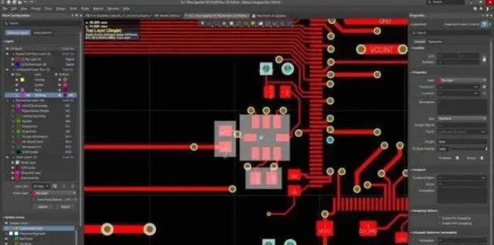
Figure 1 Altium Designer
PCB Electronic Circuit Technology
Interference from the circuit itself is not the only threat to signal quality. PCBs in automobiles are bombarded by noise, which interacts with the vehicle body in complex ways and induces unwanted currents in the circuit. Voltage spikes and fluctuations caused by the vehicle's ignition system can push components far beyond their processing tolerances.
Software Issues
Today's PCB layout tools must have a diverse combination of functions to meet the requirements of designers. Selecting the right layout tool should be the primary consideration in PCB design and must never be overlooked. Products offered by Mentor Graphics, OrCAD Systems and Altium are among the leading PCB layout tools on the market today.
Altium Designer is one of the high-end PCB design software packages on the market today. It features an automatic routing function, supports trace length tuning and 3D modeling. Altium Designer includes tools for all circuit design tasks, from schematic capture to HDL, as well as circuit simulation, signal analysis, PCB design, and FPGA embedded development (Figure 1).
Mentor Graphics' PCB layout platform addresses the key challenges faced by today's system designers: accurate, performance-oriented and reuse-driven floorplanning; efficient routing for dense and complex topologies; and electromechanical optimization. A key feature of the platform and a critical innovation in the industry is the Sketch Router, which provides designers with full interactive control over the automatic/assisted routing process, delivering results of the same quality as manual routing in a fraction of the time.
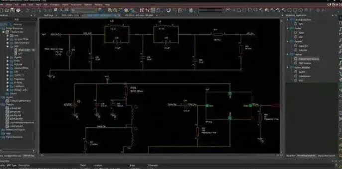
Figure 2 OrCAD PCB Editor
PCB Electronic Circuit Technology
OrCAD PCB Editor is an interactive environment developed for circuit board design at any technical level, from simple to complex. Thanks to its true scalability to the PCB solution of Cadence Allegro PCB Designer, OrCAD PCB Editor supports the technical development of design teams, enabling the management of constraints (high-speed, signal integrity, etc.) while maintaining the same graphical interface and file format (Figure 2).
Gerber Files
The industry-standard Gerber file format is used to convey design information for PCB production. In many ways, Gerber is analogous to PDF in electronic products; it is simply a compact file format written in hybrid machine control language. These files are generated by the circuit design software and sent to the PCB manufacturer for upload into CAM software.
The safe integration of electronic systems into vehicles and other complex systems raises important considerations for both hardware and software. Engineers aim to minimize the number of design iterations and development time, which delivers significant advantages for designers implementing streamlined workflows.
About Maxipcb
Maxipcb empowers innovators to turn cutting-edge technologies into reality.
We offer one-stop solutions for design, simulation, testing, PCB manufacturing, component procurement and SMT assembly, enabling efficient development, rapid deployment and risk control across the full product lifecycle.Serving the world in communications, industrial automation, aerospace, automotive, semiconductor and beyond, we build a safer, more connected future together.

 Figure 1 Altium Designer
PCB Electronic Circuit Technology
Figure 1 Altium Designer
PCB Electronic Circuit Technology Figure 2 OrCAD PCB Editor
PCB Electronic Circuit Technology
Figure 2 OrCAD PCB Editor
PCB Electronic Circuit Technology