In recent days, the crash of China Eastern Airlines flight MU5735 has touched the hearts of people across the country. Currently, in addition to full-scale search and rescue efforts, identifying the cause of the accident is a top priority—and the key to uncovering the truth lies with the black box. We hope the black box will be found soon to restore the full picture of the accident.
In recent days, the crash of China Eastern Airlines flight MU5735 has touched the hearts of people across the country. Currently, in addition to full-scale search and rescue efforts, identifying the cause of the accident is a top priority—and the key to uncovering the truth lies with the black box. We hope the black box will be found soon to restore the full picture of the accident.
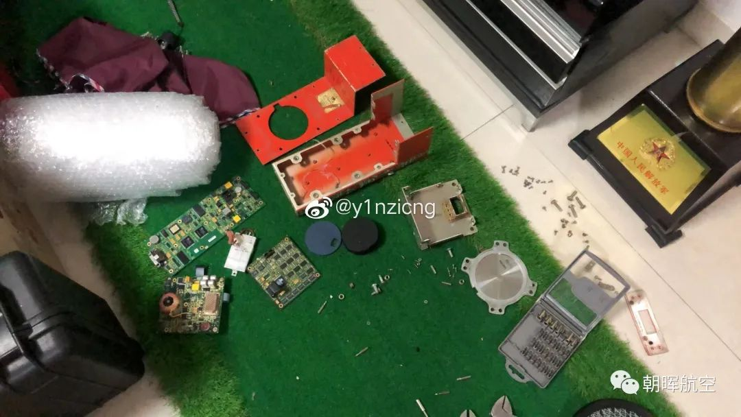
Today, I will share the disassembly process of the FA2100 Cockpit Voice Recorder (CVR). A brief background: this CVR was found at a landfill. I disassembled it purely for research purposes and didn’t initially plan to document the process, so only a few photos were taken casually. Much of the information in this article was obtained through research. I am not familiar with circuits, so please feel free to correct any mistakes below—your expertise is greatly appreciated.
Preliminary Questions Answered
Before diving into the disassembly, let’s address two common questions:
- Why are black boxes orange? As most people might guess, orange has high visibility, making it easier to locate—especially since it stores crucial flight data.
- Why are they called "black boxes"? A widely accepted explanation is that their working principle is relatively simple: data is input, but the internal processes are opaque, similar to a "blind box."
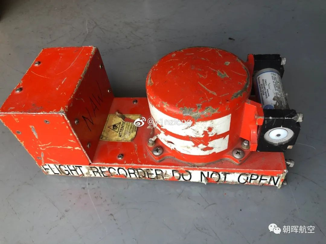
Another question people might ask: Is this the black box from the crashed aircraft? If it were, it would look like this:
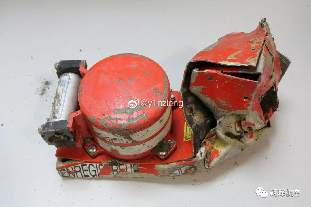
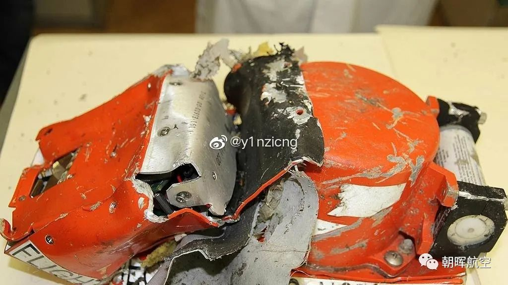
Rest assured—this is a normally decommissioned black box.
Additional Background: FDR vs. CVR
Aircraft are equipped with two main black boxes:
- FDR (Flight Data Recorder): Also commonly referred to as the "black box," it records various flight parameters during operation. It is the most important direct evidence in air crash investigations.
- CVR (Cockpit Voice Recorder): Essentially a recording device that captures radio communications, pilot conversations, and ambient sounds in the cockpit.
Unfortunately, the unit disassembled here is a CVR (not an FDR), so its structure appears relatively simple. A CVR generally consists of three parts:
- FDAU (Flight Data Acquisition Unit): The angular base section that communicates with the aircraft’s data bus to acquire and encode relevant data.
- CSMU (Crash-Survivable Memory Unit): The orange cylindrical component above the base, which is the actual data storage module—accounting for 70% of the black box’s weight.
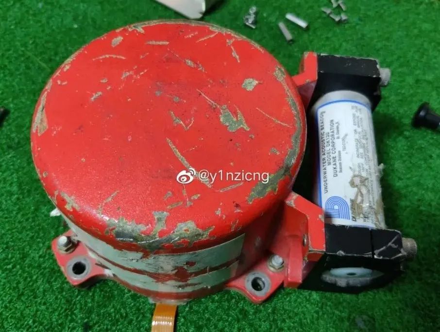
- ULD (Underwater Locator Device): A small cylinder attached to the CSMU that automatically activates and emits positioning signals when submerged in water.
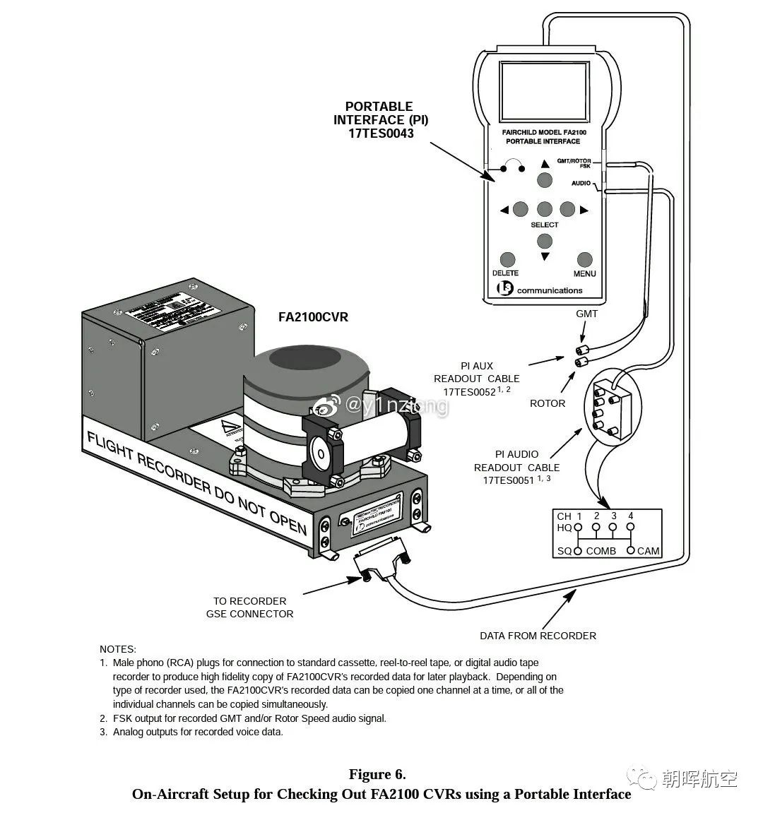
Disassembled Model: L-3 Communications FA2100 CVR
The CVR disassembled here is the FA2100 model from L-3 Communications, with the following appearance:
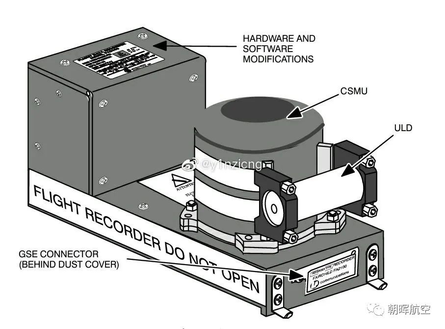
It is small in size but surprisingly heavy—most of the weight is concentrated in the protruding CSMU.
Key Design Specifications of the FA2100 CVR
It can operate in a temperature range of -55℃ to 70℃ and withstand:
- 5,000 pounds of pressure
- Continuous high temperature of 1,100℃ for 1 hour
- Continuous high temperature of 260℃ for 10 hours
- Impact acceleration of 3,400G
without any data loss. In short, it’s an extremely rugged "USB drive"!
Now, let’s move on to the disassembly to see what’s inside!
Disassembly Process
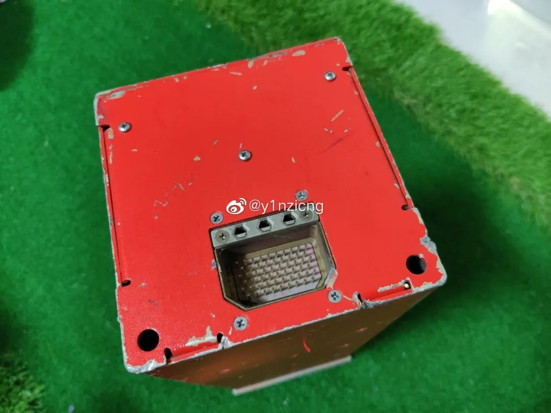
Step 1: Remove the Protective Cover and Mounting Screws
First, remove the protective cover of the maintenance port, then unscrew the surrounding screws that secure the CVR itself.
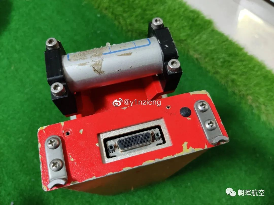
Step 2: Detach the CSMU
After removing all external screws, it was discovered that the CSMU must be removed first to access the FDAU’s top cover. Four large bolts were unscrewed, and the CSMU was lifted vertically before disconnecting the connecting cable to fully remove it.
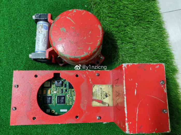
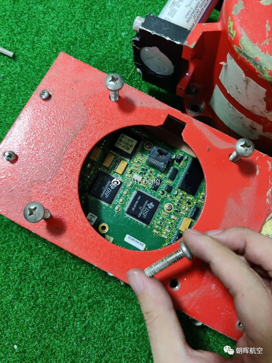
Step 3: Access the Internal PCBs
With the CSMU removed, two TI DSP chips were visible at first glance (more on these later). Next, the top cover was lifted and set aside, and the screws securing the PCB were removed to extract the entire base plate. The board appeared dirty but was actually clean—fully potted with a resin-like material (the reason for potting is self-evident: waterproofing, shock resistance, and protection).
Additional boards were found on the interface side, so disassembly continued:
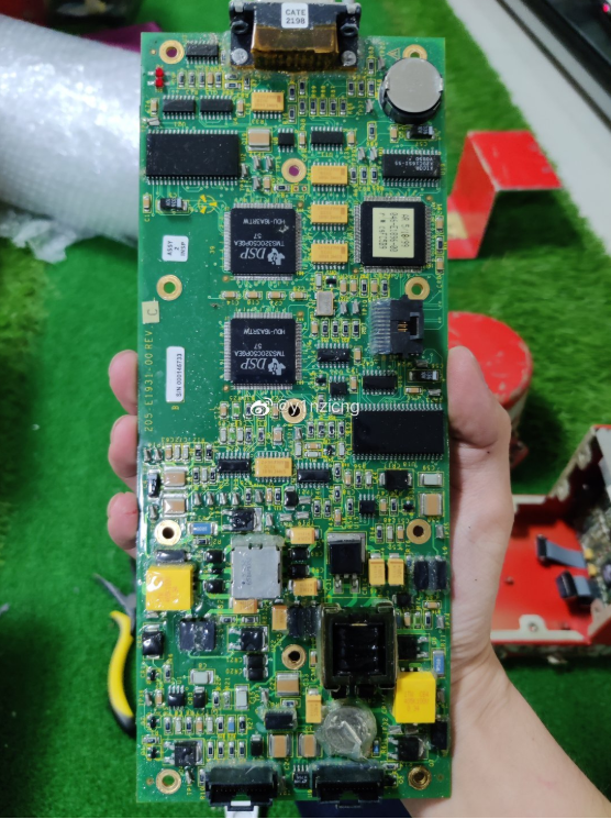
Step 4: Analyze the Two Main Boards
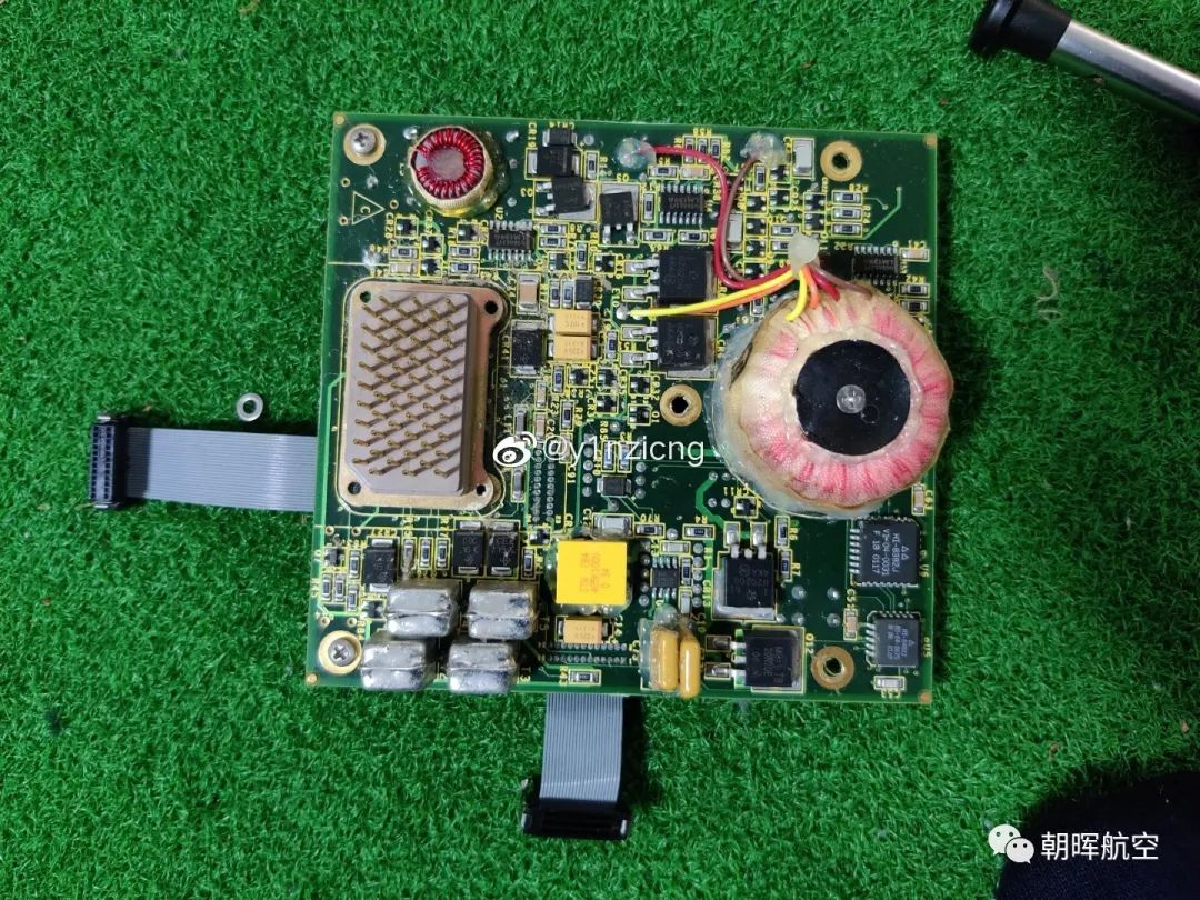
- First Board: Primarily contains logic circuits with a main control chip in the center.
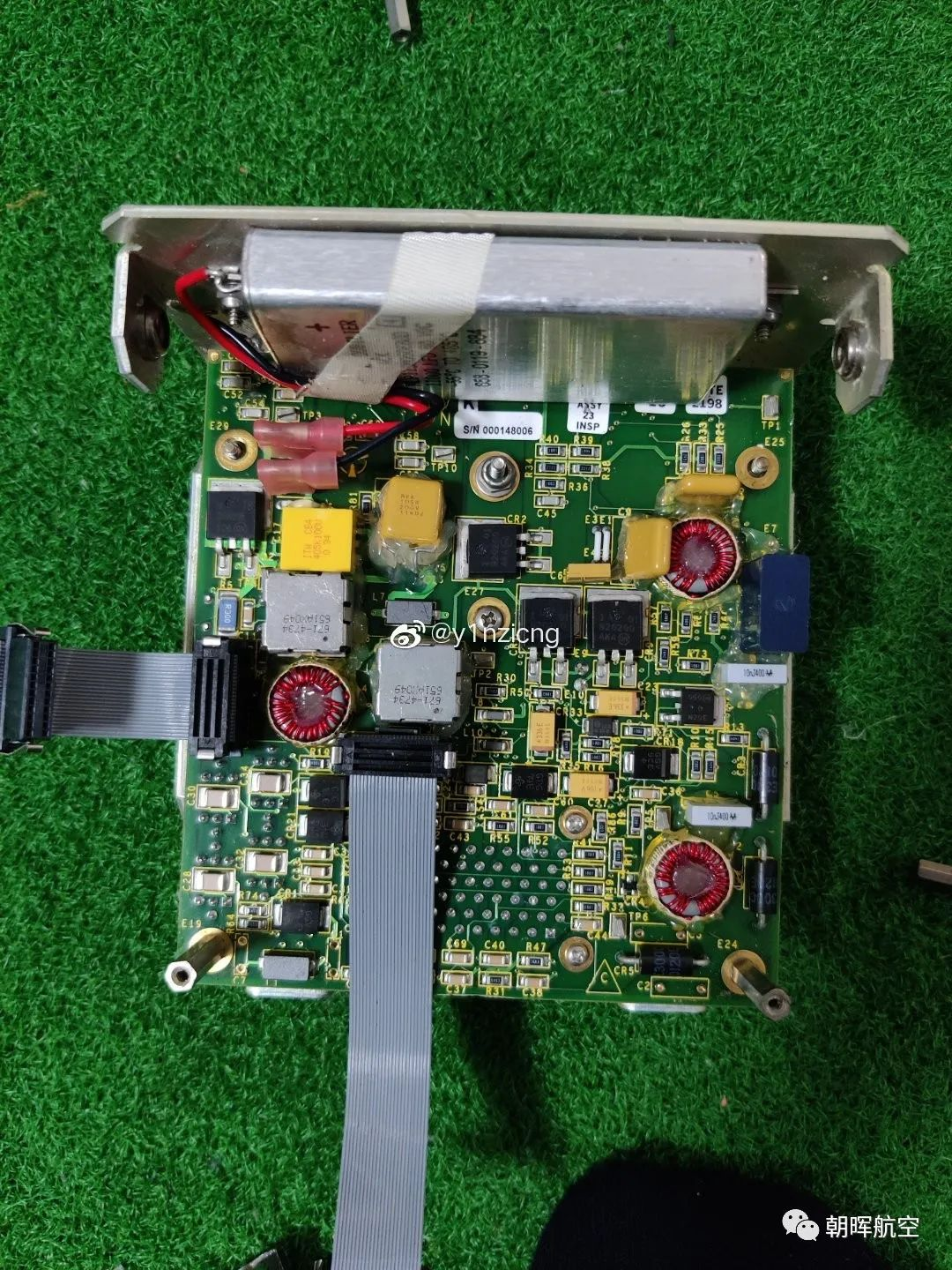
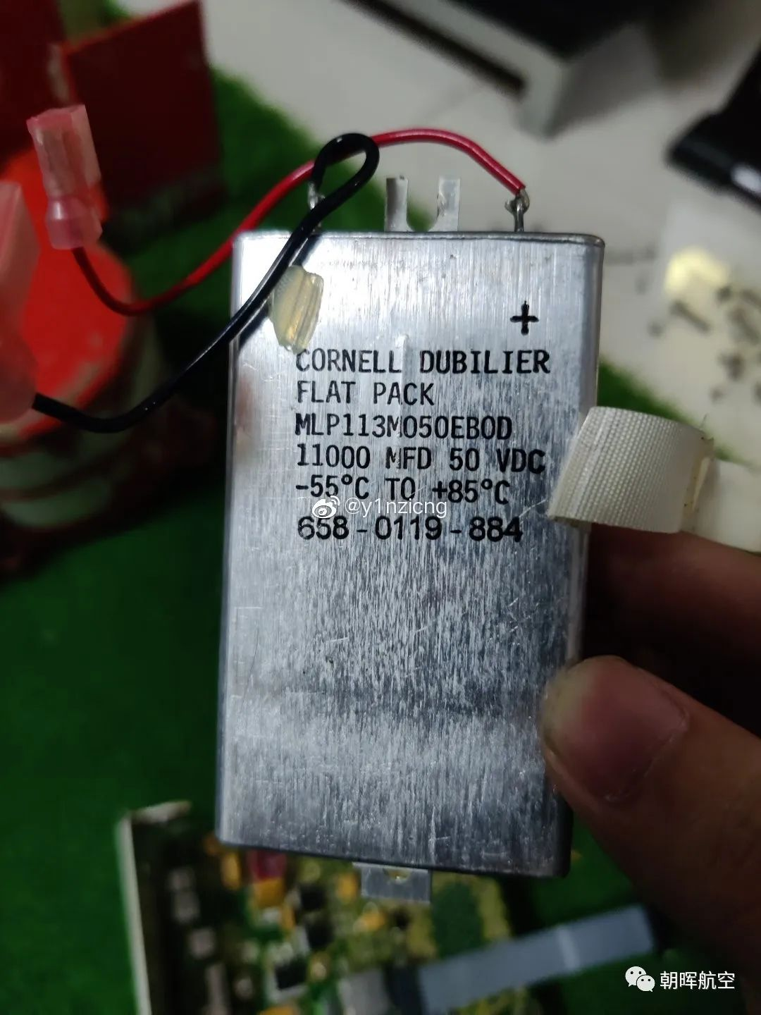
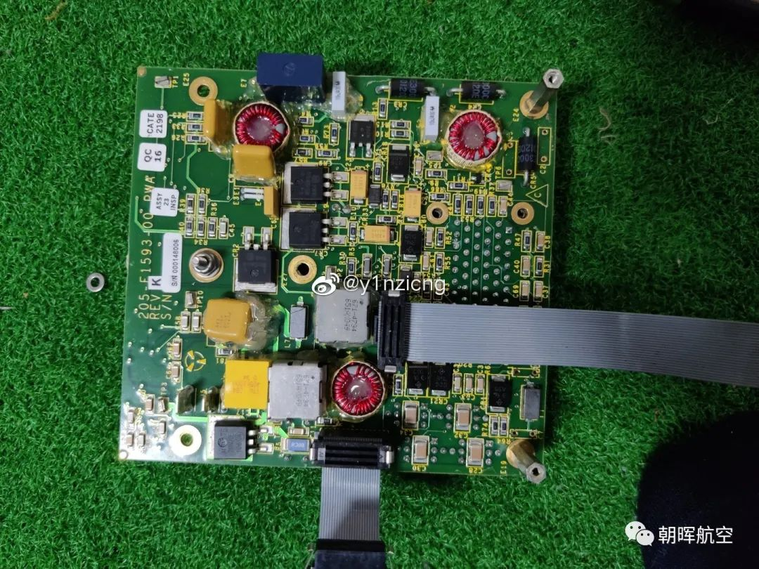
- Second Board: Clearly a power supply board (easily identifiable by its components).
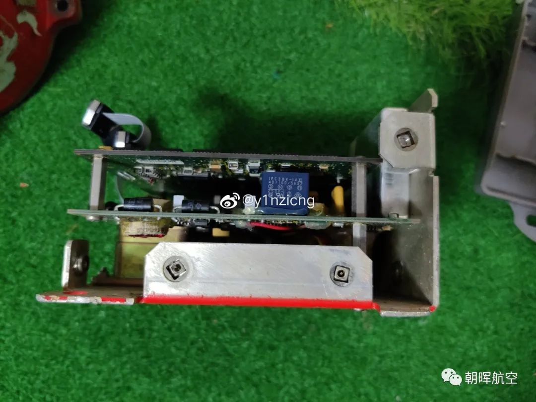
The reverse side of the power supply board contained additional power-related circuits and a compact toroidal transformer—unsurprising given the CVR’s ability to operate on both 28V DC and 115V AC.
All boards were fully potted without exception, providing protection against liquid damage. Boards were connected via connectors for easy maintenance and replacement.
Step 5: Disassemble the CSMU (Critical Data Storage Module)
Given its late-20th-century manufacturing date, it was likely equipped with solid-state storage.
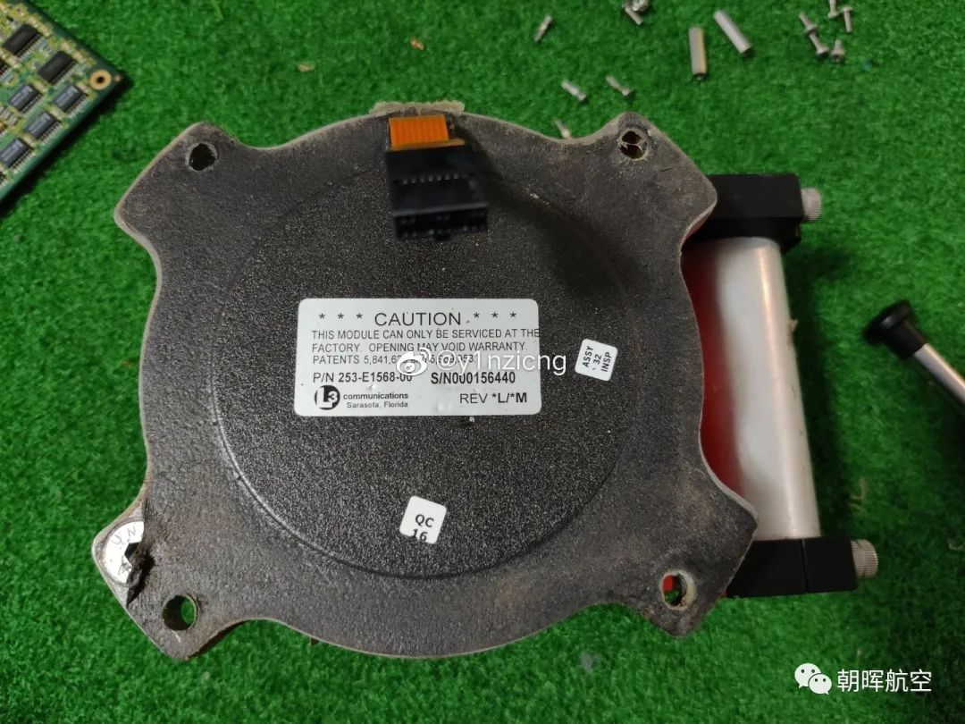
After removing the shock-absorbing foam at the bottom, four large screws were exposed and unscrewed (again, a laborious process with ordinary tools). The handwritten serial number on the connector matched the label—confirming manual assembly and calibration (a testament to the care invested in special equipment).
Under the cover, the CSMU’s interior featured a layer of heat and shock insulation—likely a mixture of asbestos and foam (lightweight and effective for thermal and impact protection).
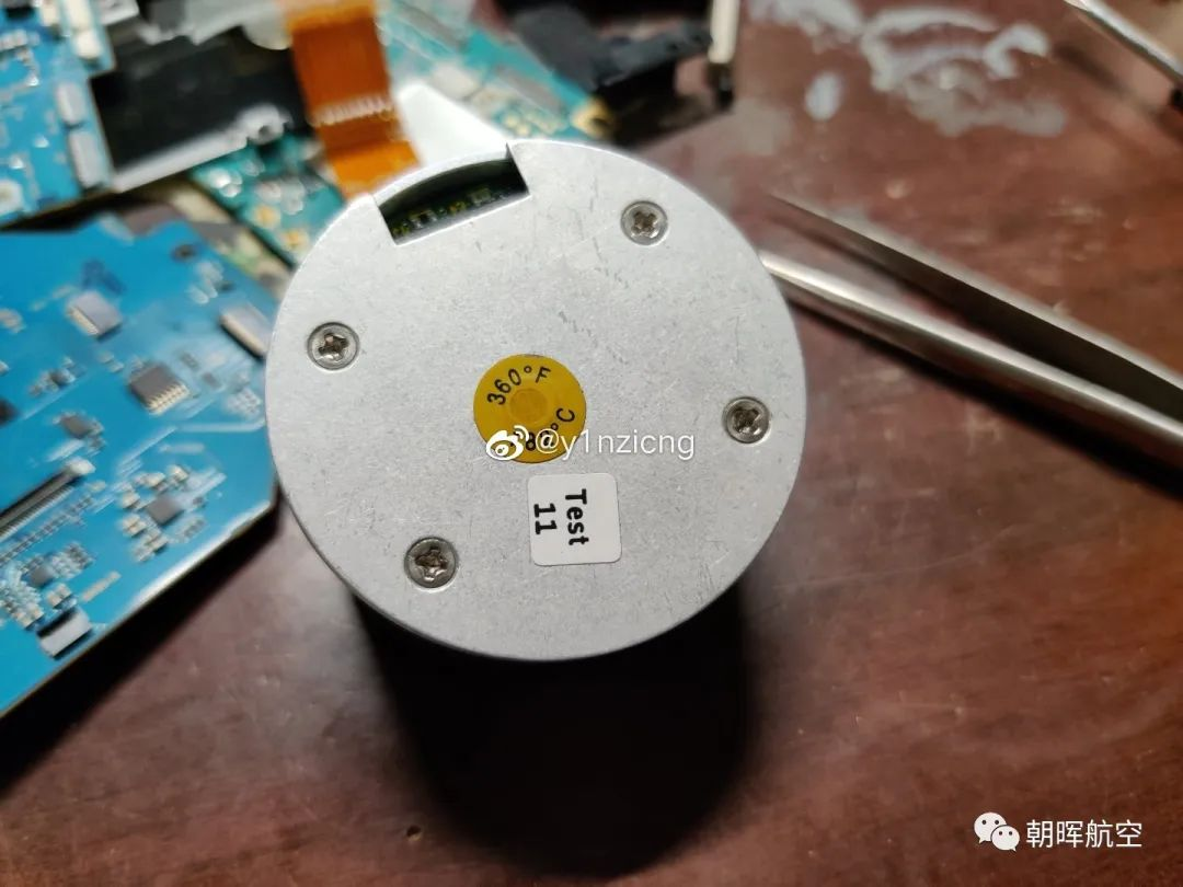
The storage module itself was smaller than expected, surrounded by black foam. To access the core components, all screws on the cylinder were removed to separate the top cover.
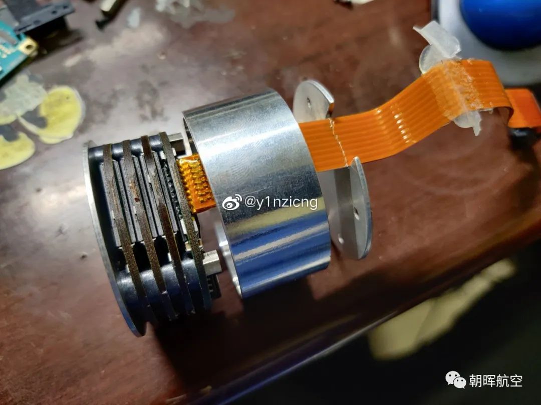
Step 6: Core Components of the CSMU
The internal structure was a multi-layer stacked assembly secured by four pillars and screws. The left side contained the main control chip, and the right side featured FLASH memory chips.
FLASH Memory Chips: The answer to the "guess the manufacturer" game—Intel!
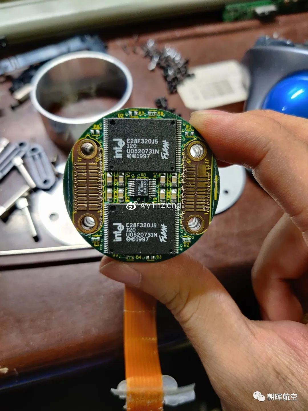
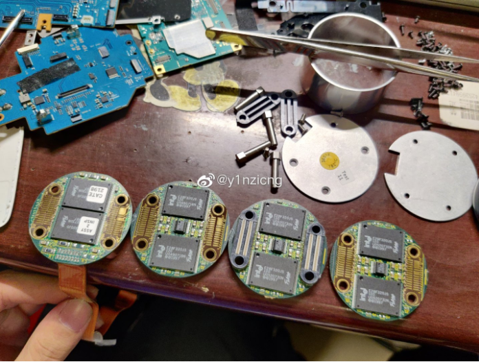
I was personally surprised by this choice—Intel chips! The modules were arranged in a row, creating an impressive sight.
According to the labels, the unit was assembled in the 21st week of 1998, using 1997-manufactured Intel SLC FLASH chips (a high-quality product in Intel’s lineup at the time). These chips supported 10,000 erase/write cycles and operated in a temperature range of 0℃ to 70℃ (wide-temperature grade). A sticker on the top cover indicated "182℃"—possibly warning that data integrity is at risk if internal temperatures exceed this threshold (exact meaning unclear).
Main Control Chip: As expected, it was a custom chip—ruling out any possibility of repurposing the module. Calculating the total storage capacity: 8 chips × 15 MB = 120 MB, which is sufficient to record 4 channels of 30-minute audio (approximately 1 MB per minute).
Step 7: Additional Chip Analysis (FDAU Section)
Returning to the earlier view of the FDAU:
- The two TI chips are DSPs responsible for processing analog microphone signals (one chip handling two channels).
- The black chips at the top-left and bottom-right of the DSPs are DRAM caches for the DSPs.
- The central labeled chip is the FDAU’s main controller from QuickLogic—essentially a highly customized ASIC similar to modern FPGAs but with less flexibility (a purpose-built chip).
- Several other key chips are also manufactured by QuickLogic, indicating the use of an integrated solution.
Final Note on Data Retrieval
I previously considered purchasing maintenance tools to read the data, but a quick online search revealed the cheapest quote was around $40,000—so I decided to disassemble it directly instead!
Conclusion
The disassembled remains show that the CVR’s structure is not overly complex. What stood out most was its robust construction and thoughtful design details. In the future, I hope to obtain an FDR for disassembly—solid-state CVRs are relatively simple in comparison.