With the rapid development of technologies such as 5G and the Internet of Vehicles, signal transmission speeds are getting faster, and the supply voltage of integrated circuit chips is consequently becoming lower.
1 Challenges of Evolving Technologies for Chip Voltage Testing
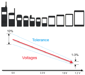
With the rapid development of technologies such as 5G and the Internet of Vehicles, signal transmission speeds are getting faster, and the supply voltage of integrated circuit chips is consequently becoming lower. In the early days, chip power supply was usually 5V and 3.3V, while the supply voltage of high-speed ICs now has dropped to 2.5V, 1.8V or 1.5V, and the core voltage of some chips is even as low as 1V. The lower the chip's supply voltage, the more stringent the tolerance for voltage fluctuations. Voltage testing for such high-speed chips with low supply voltages is represented by power supply noise, with test requirements tightened from ±5% to ±1.5% and even lower.
Challenges of evolving technologies for chip voltage testing
If the chip's power supply noise fails to meet the specification requirements, it will affect product performance and even the reliability of the entire equipment. Therefore, engineers need to accurately measure the power supply noise of chip voltages in modern circuit products.
2 Characteristics of Chip Power Supply Noise
2.1 Smaller Amplitude and Higher Frequency
In the past, power supply noise requirements were maintained at the level of tens of millivolts, but with the reduction of chip voltages, the power supply noise of many chips has dropped to the millivolt level, and some power-sensitive chips even have requirements down to the hundred-microvolt level. Noise on DC power supplies is the main source of clock and data jitter in digital systems. The dynamic loads of chips such as processors and memory on DC power supplies change with their respective clock frequencies, and may couple high-speed transient changes and noise to the DC power supply, which contain frequency components above 1 GHz.
Compared with traditional power supplies, therefore, chip power supply noise features high frequency and small amplitude, which brings challenges for engineers to accurately measure chip power supply noise.
| Item |
Traditional SMPS Power Supply Output Characteristic Testing |
Chip Power Integrity Testing |
| Frequency Range |
Up to 350MHz |
Up to GHz |
| Noise Range |
Tens to hundreds of millivolts |
As low as mV |
Table 1: Frequency and noise ranges of traditional power supplies and chip power supplies
2.2 Noise Interference Introduced by Power Distribution Network (PDN)
To ensure the power supply of all chips on the circuit, the Power Distribution Network (PDN) is spread across the entire PCB. If the PDN is close to the PCB traces of clocks or data, changes in clocks/data will be coupled to the PDN and also become a source of power supply noise. In this case, engineers also need to locate the source of power supply noise to adjust the PCB layout and routing subsequently and reduce the interference received by the PDN.
Interference coupled from clock/data transmission lines to the power distribution network
3 Factors Affecting the Accuracy of Power Supply Noise Testing
An oscilloscope is an important instrument for power supply noise testing. To accurately measure mV-level power supply noise within the GHz bandwidth and locate the noise sources interfering with the PDN, the following factors need to be considered: the oscilloscope's base noise, probe attenuation ratio, oscilloscope offset compensation capability, probe connection method, and the oscilloscope's FFT capability, among others.
3.1 Oscilloscope Base Noise
Oscilloscopes themselves generate noise. When an oscilloscope tests power supply noise, its base noise is added to the measured power supply noise, thereby affecting the test results of power supply noise.
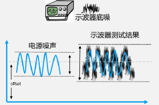
The impact of oscilloscope base noise on power supply noise test results
3.2 Probe Attenuation Ratio
At present, the most commonly used passive probes with a 500MHz bandwidth have an attenuation ratio of 10:1, which amplifies the oscilloscope's base noise and affects the uncertainty of power supply noise testing.
Using a traditional passive probe with a 1:1 attenuation ratio can avoid amplifying the oscilloscope's base noise, but such probes generally have a bandwidth of only 38MHz and cannot measure higher-frequency power supply noise, which also affects the uncertainty of power supply noise testing.
Therefore, to accurately measure power supply noise, a probe with a 1:1 attenuation ratio and a GHz-level bandwidth is required.
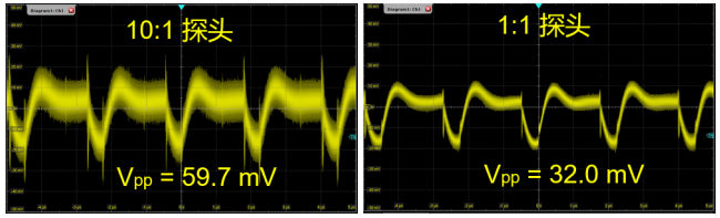
The impact of probe attenuation ratio on power supply noise testing
3.3 Oscilloscope Offset Compensation Capability
Power supply noise is noise superimposed on the chip's DC voltage. For this reason, it is necessary to set the oscilloscope's offset voltage to the same level as the DC voltage before measuring the power supply noise. For example, if a chip's supply voltage is 3.3V, first adjust the oscilloscope's offset voltage to 3.3V, then test the noise fluctuation on the 3.3V DC power supply. However, the oscilloscope's vertical range at this offset voltage will be limited, generally only up to 20mV/div, which will bring large errors when testing mV-level power supply noise.
To solve such problems, some engineers use DC-blocking capacitors to remove DC components, but this will lead to DC power supply compression and loss of low-frequency drift information. Improper selection of capacitor values will also affect high-frequency energy.
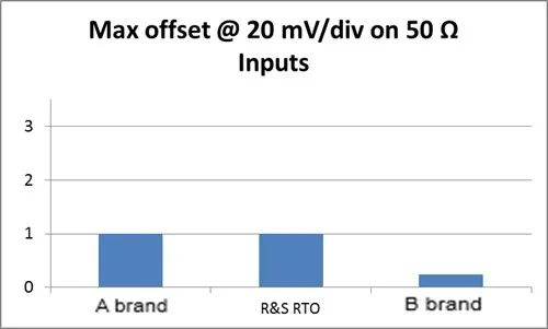
Limited oscilloscope offset compensation capability
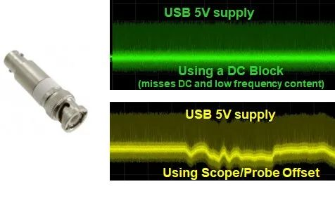
DC-blocking capacitors affect low-frequency information
3.4 Probe Connection Method
Circuits come in various forms, requiring more flexible methods for signal connection. The stability of the connection and parasitic parameters have an unignorable impact on the measured power supply circuit, so it is necessary to connect as close to the chip pins as possible and use short ground wires.
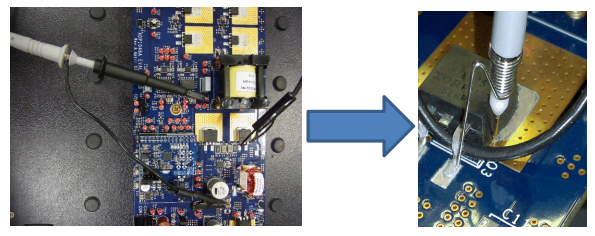
Connect close to chip pins and use short ground wires
3.5 Oscilloscope FFT Capability
Since the PDN is subject to interfering noise sources, the oscilloscope needs to have a strong FFT analysis capability to analyze the frequency of the interfering noise and then troubleshoot the source of the noise.
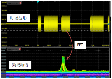
FFT analysis of power supply noise spectrum
About Maxipcb
Maxipcb empowers innovators to turn cutting-edge technologies into reality.
We offer one-stop solutions for design, simulation, testing, PCB manufacturing, component procurement and SMT assembly, enabling efficient development, rapid deployment and risk control across the full product lifecycle.Serving the world in communications, industrial automation, aerospace, automotive, semiconductor and beyond, we build a safer, more connected future together.


