Sound comes from vibration. Audible noise (20 Hz – 20 kHz) from MLCCs means the capacitor vibrates under AC voltage (typically < 1 nm displacement).
Sound comes from vibration. Audible noise (20 Hz – 20 kHz) from MLCCs means the capacitor vibrates under AC voltage (typically < 1 nm displacement).
Why Do MLCCs Vibrate?
All materials exhibit
electrostriction (expansion/contraction under electric field).
For high‑dielectric ferroelectric materials, this effect is strong and called the
piezoelectric effect.
1. Direct Piezoelectric Effect
Mechanical pressure → generates electric charge on the material surface.
2. Inverse Piezoelectric Effect (root cause of squealing)
Voltage applied → material deforms mechanically.
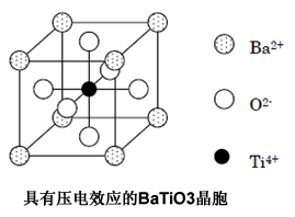
BaTiO3 unit cell structure showing piezoelectric behavior
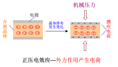
Direct piezoelectric effect diagram: pressure → charge
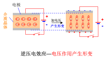
Inverse piezoelectric effect diagram: voltage → deformation
Do All MLCCs Whistle?
No — it depends on the dielectric material.
1. Paraelectric (Class I)
- Materials: SrZrO3, MgTiO3
- Examples: NPO/COG
- No whistling — very small electrostrictive deformation.
2. Ferroelectric (Class II)
- Materials: BaTiO3, BaSrTiO3
- Examples: X7R, X5R
- Whistles loudly under large AC voltage due to strong piezoelectricity.
When AC voltage is applied, the ceramic expands/contracts, transferring vibration to the PCB. If the frequency falls in 20 Hz – 20 kHz, you hear a squeal.
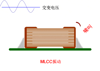
Vibration mechanism of X7R MLCC causing PCB resonance and noise
Common Applications Where Squealing Occurs
- Switching power supplies
- AC‑DC converters
- High‑frequency power circuits
Solutions to Reduce Capacitor Whistling
All methods add cost but eliminate audible noise.
-
Replace with non‑piezoelectric capacitors
Use film capacitors, tantalum capacitors, or Class I ceramic capacitors.
-
Modify the circuit
Reduce large AC voltage across the capacitor, or shift frequency out of the audible band (especially 1 kHz – 3 kHz).
-
Improve PCB design
Optimize stackup, layout, and rigidity to reduce resonance.
-
Use low‑noise / silent MLCCs
Low‑Noise MLCC Design Methods
①
Thickened bottom protection layer
Reduces deformation transfer to the PCB.
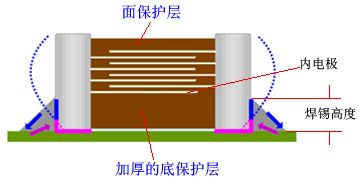
Cross‑section showing thickened bottom dielectric layer
②
Metal frame / standoff structure
Isolates the capacitor body from the PCB to absorb vibration.
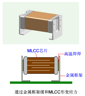
Metal bracket structure suspending MLCC
③
Weak‑piezo dielectric materials
Doped BaTiO3 with reduced piezoelectric effect (slightly lower dielectric constant).
About Maxipcb
Maxipcb empowers innovators to turn cutting-edge technologies into reality.
We offer one-stop solutions for design, simulation, testing, PCB manufacturing, component procurement and SMT assembly, enabling efficient development, rapid deployment and risk control across the full product lifecycle.Serving the world in communications, industrial automation, aerospace, automotive, semiconductor and beyond, we build a safer, more connected future together.


