As complexity and density continue to rise, the long-term reliability of RF/microwave circuit assemblies has become increasingly difficult to characterize. Printed circuit boards (PCBs) contain numerous active and passive components whose performance degrades over time and with operating temperature.
Preface
As complexity and density continue to rise, the long-term reliability of RF/microwave circuit assemblies has become increasingly difficult to characterize. Printed circuit boards (PCBs) contain numerous active and passive components whose performance degrades over time and with operating temperature. In addition, PCB substrate materials—including dielectrics, copper foil conductors, solder mask coatings, and final finishes—change over time, with operating conditions accelerating these effects. At higher frequencies, electrical performance may degrade over time, leading to power and efficiency losses. Such degradation can occur in both the short and long term. Long-term changes in circuit material and PCB performance are primarily driven by thermal effects, such as operation in high-temperature environments.
Short-term exposure to high temperatures (e.g., reflow soldering during PCB assembly) generally does not affect the electrical performance of circuit materials or PCBs. However, electrical performance degrades when temperatures exceed the Relative Thermal Index (RTI) of the circuit material or the Maximum Operating Temperature (MOT) of the PCB. Exposure above the Thermal Decomposition Temperature (Td) of the circuit material—even for a few minutes—causes permanent changes in electrical properties.
RTI is a temperature-based material parameter defining the maximum temperature at which a circuit material retains its key properties without degradation. MOT is a UL-certified board-level parameter applicable to the complete PCB (dielectric and conductor layers). These two parameters both define maximum temperature limits: RTI applies to the raw circuit material (e.g., laminate), while MOT applies to the finished PCB. The MOT of a circuit will never exceed the RTI of its substrate, as UL will not certify a MOT higher than the material’s RTI.
High-frequency circuit laminates consist of dielectric materials and copper foil conductors, based on either thermoplastic or thermoset resins. Thermoplastics are typically soft and flexible, while thermosets are rigid and stiff. Thermoplastics can be heated to melting or reflow temperatures, whereas thermosets cannot and will decompose at sufficiently high temperatures.
Thermoplastic materials for RF/microwave/mmWave PCBs are commonly PTFE-based. While other materials may be used alone or blended with PTFE, most RF/microwave/mmWave PCBs employ PTFE in some form. Thermoset materials for RF PCBs are typically hydrocarbon or polyphenylene ether (PPE/PPO) polymer resins, chosen for dimensional stability and cost efficiency.
PTFE-based thermoplastic circuit materials are widely recognized for stable electrical performance under long-term and high-temperature operating conditions. In contrast, circuits made from hydrocarbon or PPE-based thermoset materials exhibit electrical performance drift over time and temperature, with the magnitude of change dependent on the material formulation.
Nearly pure PTFE materials (e.g., Rogers RT/duroid 5880 laminate) maintain extremely stable electrical properties under long-term high-temperature operation (>25°C). PTFE composites modified with fillers to adjust dielectric constant (Dk/εr) or optimize performance for mmWave applications show different aging behavior based on additive composition. For example, Rogers RO3003 laminate—a PTFE-based material with ceramic fillers and additives for automotive radar and mmWave applications—exhibits aging characteristics distinct from pure PTFE materials (Figure 1).
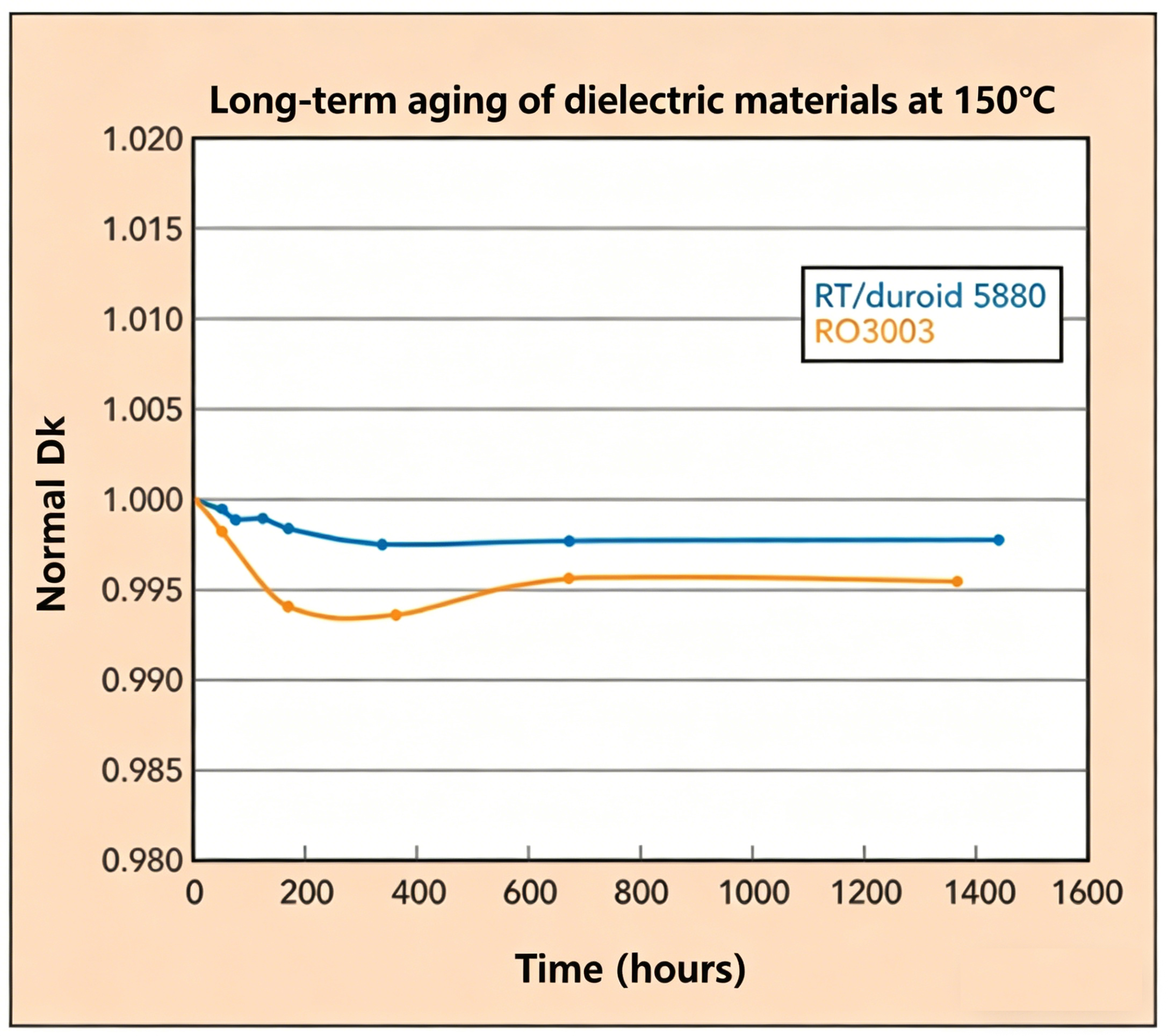
Figure 1: Long-Term Aging Comparison of Dielectrics in RT/duroid 5880 and RO3003 Laminates
Both materials show minimal thermal aging: Dk/εr changes are less than 1%. An initial Dk drop occurs in both materials due to moisture loss at 150°C. Although both are low-hygroscopic, they retain trace moisture at the microscopic level before testing; high-temperature drying removes this moisture and reduces Dk. The more complex PTFE formulation of RO3003 responds differently to high-temperature drying than RT/duroid 5880. Nevertheless, long-term aging at 150°C results in less than 1% Dk variation, confirming excellent stability.
Thermoset materials exhibit larger Dk shifts than thermoplastics under long-term high-temperature exposure. The magnitude of Dk change is highly formulation-dependent, and the underlying mechanism differs significantly from thermoplastics.
Thermoset circuit materials naturally oxidize at high temperatures. Oxidation proceeds slowly at room temperature but accelerates rapidly with heat. Oxidation in thermoset substrates is limited by penetration depth; surface reactions slow as oxide layers accumulate, eventually halting the process. Oxidation rate and penetration depth depend on material formulation, with antioxidant (AO) additives used to slow degradation (effectiveness varies by formulation).
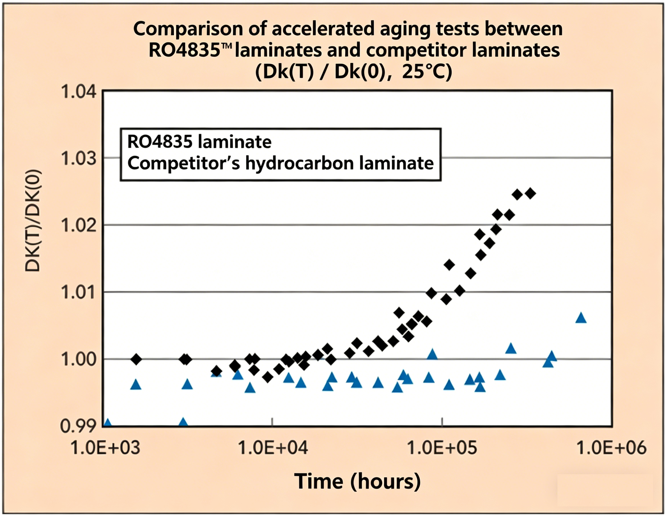
Figure 2: Long-Term Aging Comparison of Thermoset Hydrocarbon Circuit Materials at 25°C
Figure 2 compares two hydrocarbon thermoset laminates: one with poor oxidation resistance and one optimized with high-performance AO additives for robust long-term stability. The benefit of AO addition is evident in Dk stability over time. Data were measured via the
X-band fixed stripline resonator method (per IPC-TM-650 2.5.5.5c) at 10GHz, with samples fully exposed to ambient conditions. Values are extrapolated to longer times using the Arrhenius equation for accelerated aging evaluation. The test compares a standard hydrocarbon laminate with Rogers RO4835 (inheriting electrical performance from RO4350B, a reliable high-power RF/microwave substrate). For reference, 1.0E+05 hours = 11.4 years.
When evaluating aged materials in circuit form, aging effects differ because copper layers shield the dielectric from oxidation. The degree of protection varies by transmission line structure (Figure 3).
Figure 3: Simplified Side Views of Common RF Structures and Oxide Penetration into Thermoset Dielectrics
Oxidation forms primarily on exposed dielectric surfaces, with minor penetration under copper conductors. Most oxidation remains surface-localized, with a decreasing gradient into the bulk material.
Oxidation increases both dielectric constant (Dk) and dissipation factor (Df). Several factors govern the impact of oxidation on RF/microwave/mmWave performance:
- Thinner dielectrics are more severely affected, as oxidation occupies a larger volume fraction.
- Impact varies by circuit structure based on electromagnetic (EM) field distribution:
- Stripline: Nearly immune to oxidation (EM fields are fully enclosed).
- Microstrip: Most EM fields reside between the signal conductor and ground plane; edge fields are sensitive to oxidation (effects become detectable at mmWave frequencies, with thinner substrates more vulnerable).
- Edge-coupled microstrip: Coupled fields intersect surface oxide layers, degrading RF performance.
- Grounded coplanar waveguide (GCPW) on thin substrates: Significantly affected by oxidation at mmWave frequencies.
Dielectric Property Characterization
Aging tests employed the X-band fixed stripline resonator method (IPC-TM-650 2.5.5.5c) to characterize dielectric properties. Fully exposed dielectrics oxidize on all surfaces during testing (eight surfaces in the stripline fixture). Oxidation levels are far higher than in circuit-form testing, where copper provides shielding.
RO4835 laminate is formulated with an optimized AO package to resist oxidation. It shares the same base formulation as RO4350B, a proven reliable substrate for high-power RF/microwave circuits. The AO system extends the time to reach equivalent oxidation levels by 10× compared to RO4350B.
Beyond oxidation resistance, RO4350B delivers excellent long-term aging performance in high-power applications. Most aging-related issues occur in coupled circuits (e.g., directional couplers). To isolate structural effects, tests compared circuit-form samples with fully etched (copper-free) dielectric samples of the same material.
Tests included multiple circuit structures on Rogers RO4350B and RO4350B LoPro laminates: 50Ω microstrip, edge-coupled microstrip bandpass filters, and step-impedance low-pass filters. RO4350B LoPro is identical to standard RO4350B but uses ultra-smooth low-profile copper foil to reduce insertion loss at RF/microwave/mmWave frequencies.
Figure 4: Comparison of Bare Dielectric (Fully Etched) vs. 50 Ω Microstrip Circuits on 20-mil RO4350B (Std) and 20-mil RO4350B LoPro (LoPro) Laminates
Figure 4 summarizes long-term aging effects. The largest Dk shift occurs in fully etched (bare dielectric) samples tested at 50°C in an X-band stripline fixture. Circuit-form 50Ω microstrip samples show drastically smaller Dk changes across temperatures.
Circuit-form samples require 10–100× longer exposure to reach the same oxidation level as bare dielectrics. Figure 4 also shows oxidation and Dk variation across temperatures. Substrate thickness further modulates oxidation sensitivity.
Step-impedance low-pass filters behave similarly to microstrip transmission lines. Edge-coupled bandpass filters show greater oxidation sensitivity, requiring 3–5× longer exposure to match bare dielectric oxidation. Tightly coupled circuits are more sensitive than loosely coupled designs. Higher temperatures increase the rate of Dk divergence due to oxidation.
Coatings applied to circuits reduce thermoset oxidation:
- Solder mask significantly reduces aging but may degrade RF performance.
- Parylene coating (≥25μm thickness) minimizes long-term oxidative aging.
- HumiSeal conformal coatings reduce oxidation (effectiveness varies by type).
Conclusion
Circuit materials experience short-term high-temperature exposure during manufacturing and long-term high-temperature exposure in service. Long-term thermal effects manifest as oxidation buildup in thermoset dielectrics, leading to Dk drift. Accurate, controlled testing is required to evaluate long-term aging susceptibility, as different measurement methods yield divergent results for high-frequency materials. Selecting the right test approach (material-level vs. circuit-level) ensures reliable data for Dk characterization and circuit modeling.
TMM 3-D Molded Microwave Materials
Rogers TMM thermoset microwave materials are patented ceramic-filled thermoset polymer composites designed for high-frequency applications. Available as PCB laminates or 3D molded structures, they enable innovative designs. Key properties include ultra-low TCDk, controllable Dk (3–12), low CTE, high chemical resistance, and moldability into complex shapes.
About Maxipcb
Maxipcb enables advanced electronic innovation. We deliver one-stop solutions including circuit design, simulation, testing, PCB fabrication, component sourcing and SMT&PCBA assembly, to boost R&D efficiency, speed up mass production and control full-cycle risks. We serve global sectors like communication, industrial automation, aerospace, automotive and semiconductor, jointly forging a safer, connected intelligent future.


