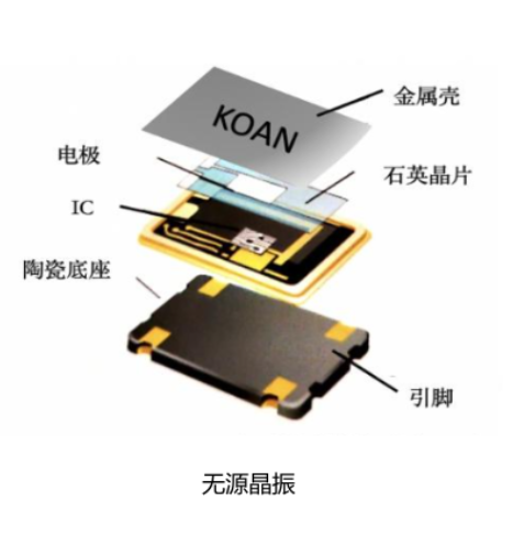
One, the classification of crystal oscillator01 passive crystal oscillatorPassive crystal oscillator is a passive oscillator, which does not need external power supply to maintain oscillation. Its oscillation frequency is determined by the physical size and material characteristics of the crystal (generally passive crystal oscillation is adopted).
 02 active crystal oscillator
Active crystal oscillator is an active oscillator, which needs external power supply to provide energy to maintain oscillation. It usually includes crystal oscillator chip and external circuit, which generates stable oscillation signal through feedback mechanism.
Second, the crystal oscillator placement rulesClose placement:The crystal oscillator package and related transistors, amplifiers or microcontrollers are placed in close proximity as much as possible to reduce the length of connecting lines and reduce the delay and loss of signal transmission.
Interference isolation:Keep the crystal oscillator circuit at a certain distance from high-frequency and high-current parts (such as processor and clock generator) to reduce the influence of electromagnetic interference on the crystal oscillator.
Ground wire short circuit:Ensure that the ground wire of the crystal oscillator is the shortest and most direct path, and avoid crossing with other signal lines to reduce the noise of the ground wire.
Reduce loops:Avoid forming a large loop around the crystal oscillator and its related circuits, because the loop will cause electromagnetic radiation and mutual interference, which will affect the stability and performance of the crystal oscillator.
Common mode interference:Try to isolate the signal lines of crystal oscillator and its related circuits from other signal lines to reduce the influence of common-mode interference on crystal oscillator signals.
Differential wiring:The differential signal transmission mode is used to reduce the interference and loss to the crystal oscillator signal and improve the anti-interference ability.
Prevent crosstalk:In PCB layout, avoid the interference between crystal oscillator signal lines and other signal lines, especially avoid the intersection with high frequency signal lines.
Electromagnetic compatibility:Follow the design principle of electromagnetic compatibility (EMC), reduce the interference of electromagnetic radiation and sensitive signals through reasonable layout and grounding design, and ensure the stability and reliability of crystal oscillator circuit.
Keep the temperature stable:Try to place the crystal oscillator in a position that is not easily affected by external temperature changes, and avoid the vicinity of heat sources or areas with poor ventilation.
About Maxipcb
Maxipcb empowers innovators to turn cutting-edge technologies into reality.
We offer one-stop solutions for design, simulation, testing, PCB manufacturing, component procurement and SMT assembly, enabling efficient development, rapid deployment and risk control across the full product lifecycle.Serving the world in communications, industrial automation, aerospace, automotive, semiconductor and beyond, we build a safer, more connected future together.

