I have shared the simulation and testing methods for crosstalk on several occasions recently, and this article is written based on the previous research. Some topological structures in this article are unclear mainly because there are too many transmission line segments in the schematic, leading to blurry screenshots in the text. I will have further discussions with you on this topic when the opportunity arises.
Editor's Note: I have shared the simulation and testing methods for crosstalk on several occasions recently, and this article is written based on the previous research. Some topological structures in this article are unclear mainly because there are too many transmission line segments in the schematic, leading to blurry screenshots in the text. I will have further discussions with you on this topic when the opportunity arises.
A great deal of content about crosstalk has been introduced before, including its origin and formation, types, simulation and testing, as well as several methods to reduce crosstalk. One of the methods is to shield important signal nets with ground nets. This added ground net is commonly referred to as a guard trace, as shown in the figure below:
Can this ground net really protect the signal net? Especially the type of ground net shown in the above figure (without ground vias). This article will discuss with you whether such a ground net is truly necessary to add.
Ordinarily, the design without guard ground or isolated ground is structured as shown in the figure below:
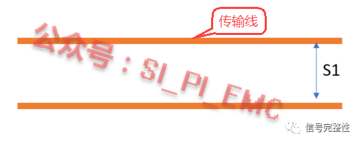 Transmission Line
The structure with guard ground added is as shown in the figure below:
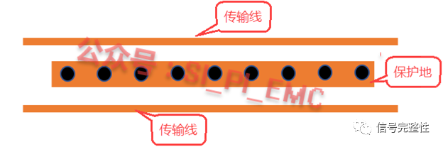 Transmission Line | Guard Ground | Transmission Line
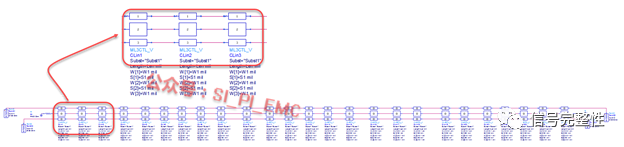
For such complex problems, we can conduct simulation analysis through modeling. A simple model can be built in ADS for qualitative research, and different structures can be modeled separately as follows.
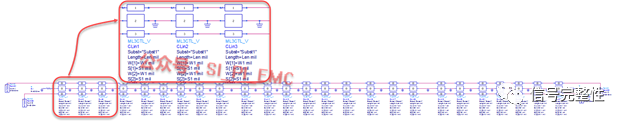
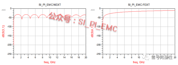
When guard ground is considered, the guard trace is generally placed at a distance of 1W (trace width) or 1H (distance from signal to reference layer) from the protected signal net, with the model shown in the figure below:
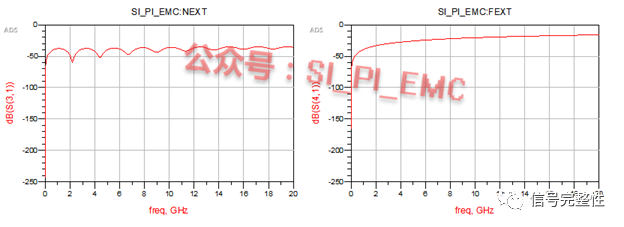
The simulation results of its near-end and far-end crosstalk are shown in the figure below:
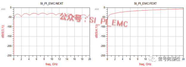 SI_PI_EMC:NEXT | SI_PI_EMC:FEXT | 0-20GHz Frequency Axis | Crosstalk (dB) Vertical Axis
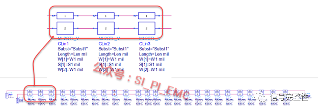
If the guard ground is connected to the ground at intervals of 1/10 wavelength (equivalent to adding ground vias), its structure is shown in the figure below:
The simulation results of its near-end and far-end crosstalk are shown in the figure below:
If the guard trace is added but not connected to the ground, its structure is shown in the figure below:

The simulation results of its near-end and far-end crosstalk are shown in the figure below:
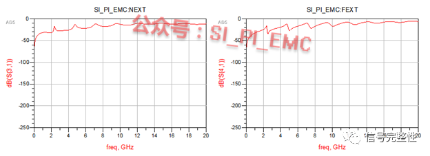 SI_PI_EMC:NEXT | SI_PI_EMC:FEXT | 0-20GHz Frequency Axis | Crosstalk (dB) Vertical Axis
For the structure without guard ground, the spacing between the two signal nets will be relatively large, with the model shown in the figure below:
 CLin1 | CLin2 | CLin3 | Subst="Subst1" | Length=Len mil | W[1]=W1mil | S[1]=S1 mil
The simulation results of its near-end and far-end crosstalk are shown in the figure below:
The four sets of simulation results are compared in the figure below, where:
- dB(S(3,1)): No guard ground trace
- dB(Guardtrace_2..S(3,1)): With guard ground trace, no ground connection in the middle
- dB(Guardtrace_2gnd..S(3,1)): With guard ground trace, grounded at 1/10 wavelength intervals
- dB(Guardtrace_open..S(3,1)): Guard ground trace with open circuit (no ground connection)
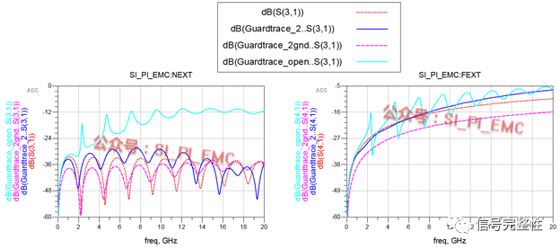 SI_PI_EMC:NEXT | SI_PI_EMC:FEXT | 0-20GHz Frequency Axis | Four Groups of Crosstalk Curves (dB) | Vertical Axis
From the comparison results, it is obvious that crosstalk is the largest when the guard ground is added but not connected to GND. Crosstalk is also relatively large if the guard ground is added but not equipped with ground vias at 1/10 wavelength intervals; crosstalk can be significantly reduced if the vias are added. Of course, if there is sufficient board space, omitting the guard ground will also yield relatively good results, but the crosstalk will be slightly higher than that of the structure with guard ground grounded at 1/10 wavelength intervals.
The above conclusions are obtained from limited experiments and are part of the recent research results on crosstalk. More results will be shared after the verification board is completed, so the conclusions are for
reference only. You are welcome to conduct further analysis and research on this topic if interested.
About Maxipcb
Maxipcb empowers innovators to turn cutting-edge technologies into reality.
We offer one-stop solutions for design, simulation, testing, PCB manufacturing, component procurement and SMT assembly, enabling efficient development, rapid deployment and risk control across the full product lifecycle.Serving the world in communications, industrial automation, aerospace, automotive, semiconductor and beyond, we build a safer, more connected future together.


 Transmission Line
 Transmission Line | Guard Ground | Transmission Line
 SI_PI_EMC:NEXT | SI_PI_EMC:FEXT | 0-20GHz Frequency Axis | Crosstalk (dB) Vertical Axis


 SI_PI_EMC:NEXT | SI_PI_EMC:FEXT | 0-20GHz Frequency Axis | Four Groups of Crosstalk Curves (dB) | Vertical Axis