A circuit composed of operational amplifiers is referred to as an op-amp circuit.
These circuits come in many types and are essential for studying analog electronics and a must-master skill for electronics engineers.
A circuit composed of operational amplifiers is referred to as an
op-amp circuit.
These circuits come in many types and are essential for studying analog electronics and a must-master skill for electronics engineers.
Instead of memorizing topologies and formulas, you should understand the core principles. When analyzing op-amp circuits, temporarily ignore terms like inverting/non-inverting amplifier, adder, subtractor, differential input, and related formulas. Also ignore parameters such as input bias current, CMRR, and offset voltage—focus on the ideal op-amp.
Most op-amp problems can be solved with two core rules: Virtual Short and Virtual Open. These are fundamental in all textbooks, but mastering them requires practice.
About Virtual Short & Virtual Open
Virtual Short
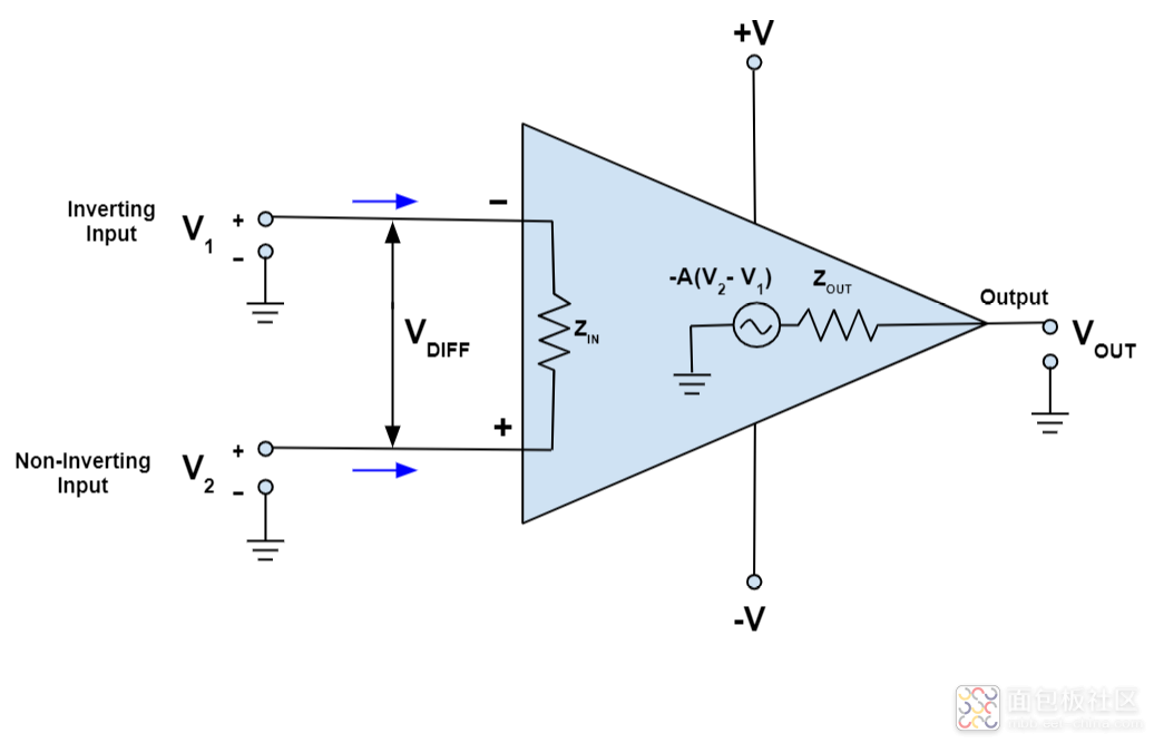
The open-loop voltage gain of a general-purpose op-amp is above 80 dB, while the output voltage is limited (typically 10–14 V). The differential input voltage is less than 1 mV, so the two input terminals are nearly at the same potential, like a “false short.”
Definition: When an op-amp operates linearly, the two inputs can be treated as equal in voltage (virtual short). They must not be physically shorted.
Virtual Open
The differential input resistance of a general-purpose op-amp is above 1 MΩ. The current into the input terminals is less than 1 μA, much smaller than external circuit current. The inputs behave like an open circuit.
Definition: When an op-amp operates linearly, the two inputs can be treated as drawing zero current (virtual open). They must not be physically disconnected.
Case 1: Inverting Amplifier
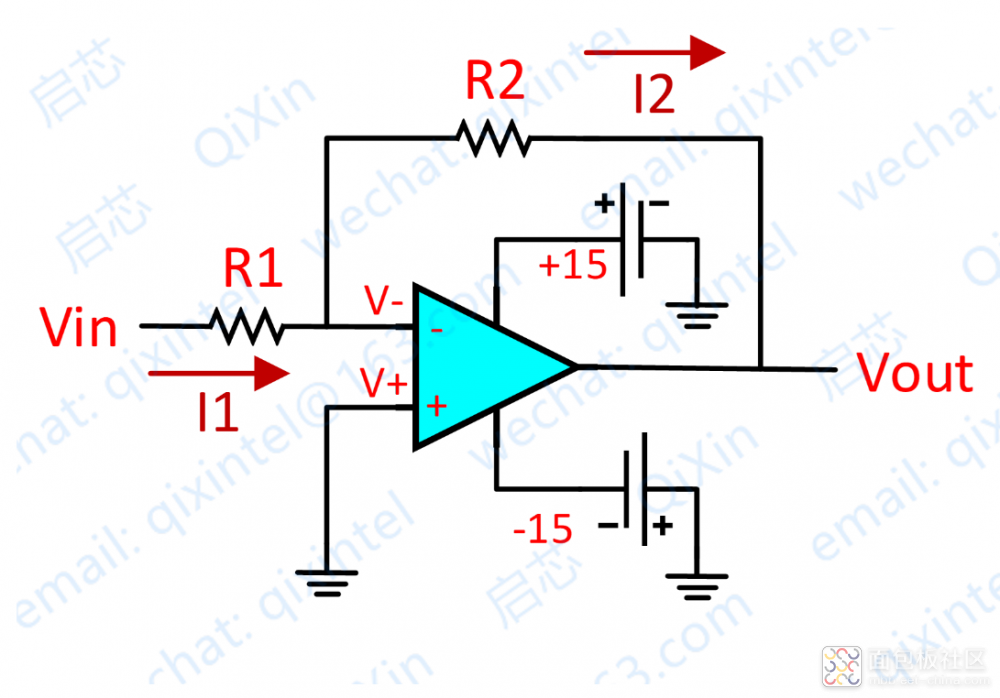
Inverting op-amp circuit diagram
Analysis:
- By virtual short: Non-inverting input = 0 V → inverting input V⁻ = 0 V.
- By virtual open: No current enters the op-amp. R₁ and R₂ are in series, so currents are equal.
- I₁ = (Vi − V⁻) / R₁
- I₂ = (V⁻ − Vout) / R₂
- V⁻ = V⁺ = 0, I₁ = I₂
- Solve: Vout = −(R₂/R₁) × Vi
This is the classic inverting proportional amplifier.
Case 2: Non-Inverting Amplifier
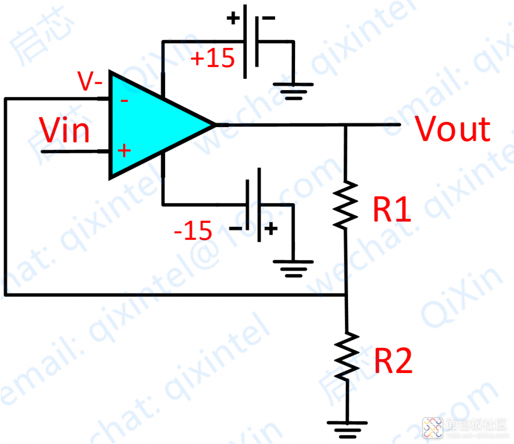
Non-inverting op-amp circuit diagram
Analysis:
- By virtual short: Vi = V⁻
- By virtual open: No current enters the op-amp. Current through R₁ = current through R₂ = I.
- I = Vout / (R₁ + R₂)
- Vi = I × R₂
- Solve: Vout = Vi × (R₁ + R₂) / R₂
This is a non-inverting amplifier.
Case 3: Inverting Adder
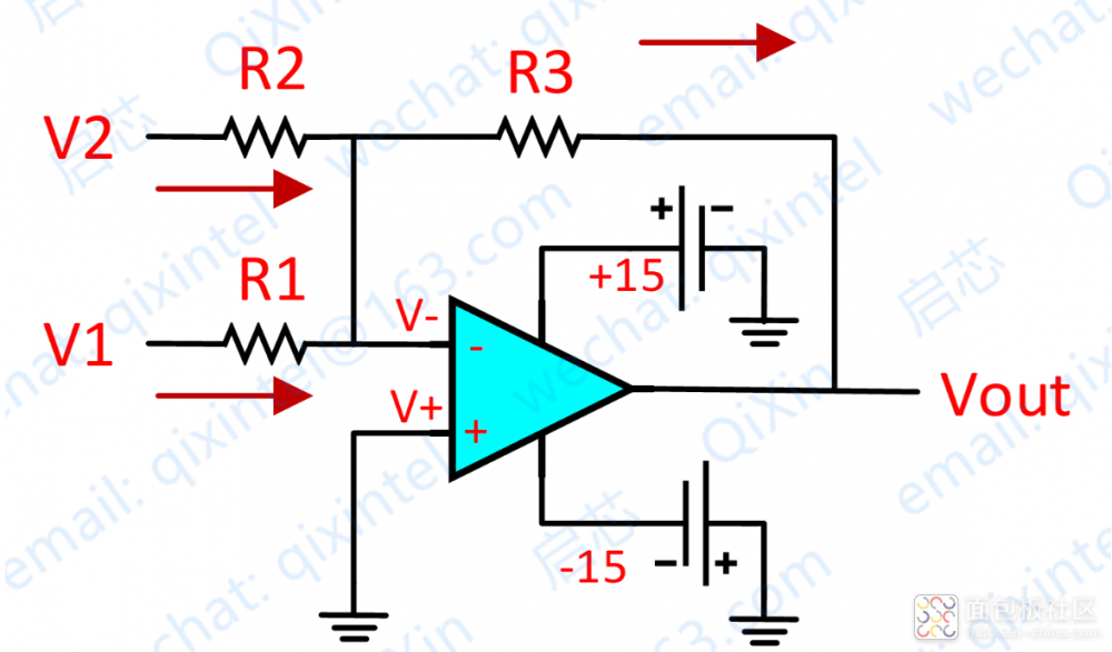
Inverting adder circuit diagram
Analysis:
- By virtual short: V⁻ = V⁺ = 0
- By virtual open and Kirchhoff’s law:
(V₁ − V⁻)/R₁ + (V₂ − V⁻)/R₂ = (Vout − V⁻)/R₃
- Simplify: V₁/R₁ + V₂/R₂ = Vout/R₃
- If R₁ = R₂ = R₃: Vout = −(V₁ + V₂)
This is an inverting adder.
Simulation Examples
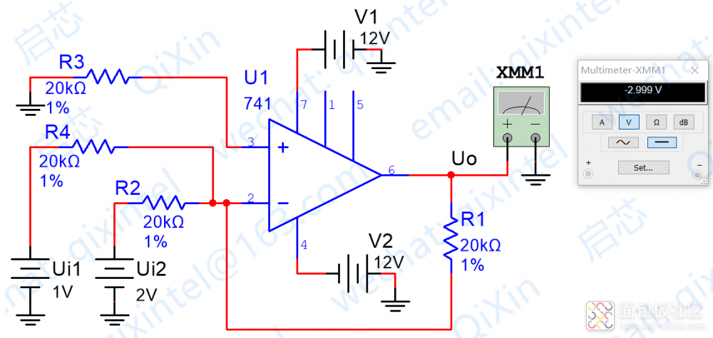
Simulation with R₁=R₂=R₄ → VO = V₁+V₂
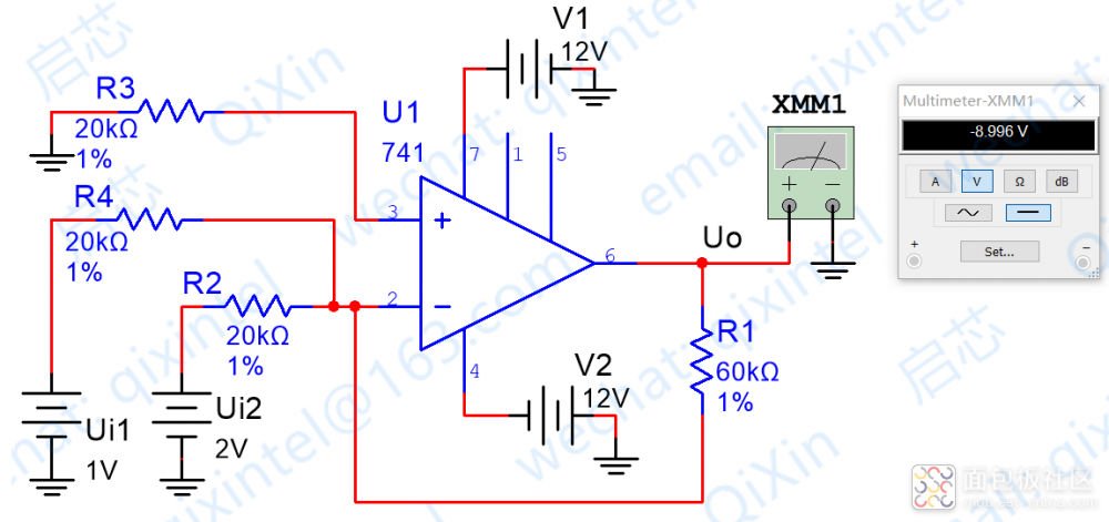
Simulation with R₂=R₄, R₁=3R₂ → VO=3(V₁+V₂)
Practical Circuit (OP07C)
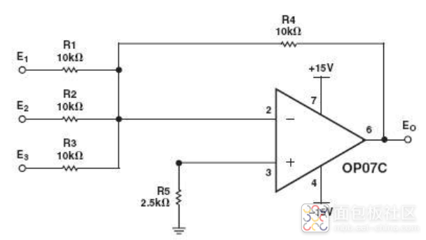
OP07C low-frequency noise amplifier circuit
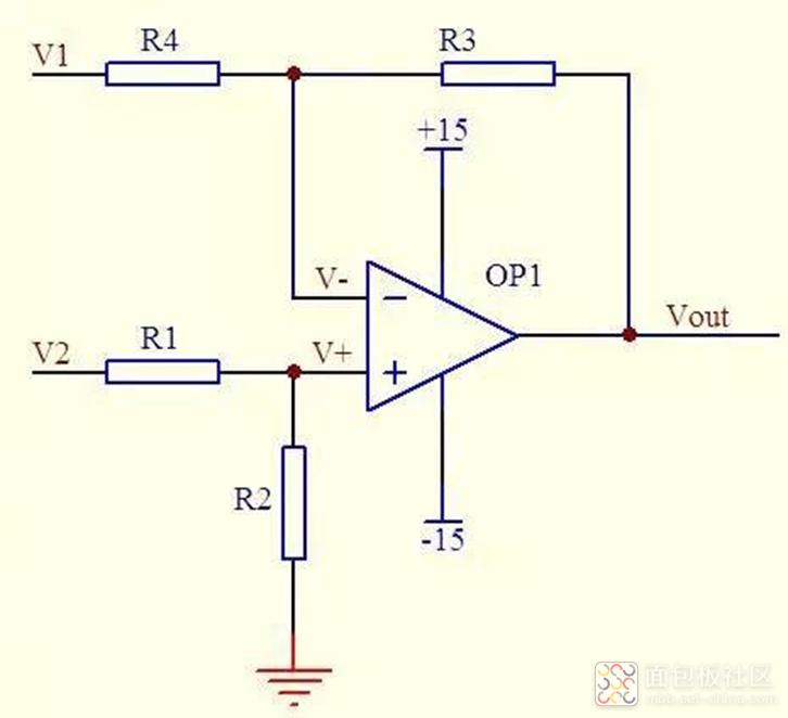
Case 4: Non-Inverting Adder
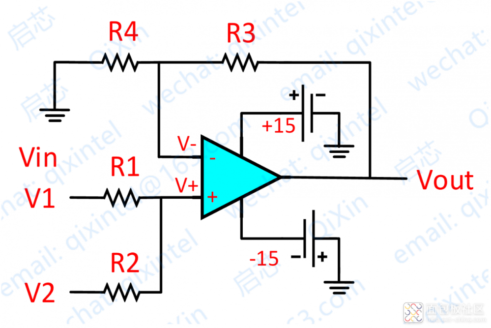
Non-inverting adder circuit diagram
Analysis:
- By virtual open: Currents through R₁=R₂; currents through R₃=R₄.
- (V₁−V⁺)/R₁ = (V⁺−V₂)/R₂
- (Vout−V⁻)/R₃ = V⁻/R₄
- By virtual short: V⁺ = V⁻
- If R₁=R₂, R₃=R₄:
V⁺ = (V₁+V₂)/2, V⁻ = Vout/2
- Result: Vout = V₁ + V₂
Summary
All basic op-amp circuits can be analyzed using virtual short and virtual open, combined with Ohm’s Law and Kirchhoff’s Laws.
Extended Circuits
Differential Subtractor
Differential subtractor circuit
Analysis gives:
Vout = V₂ − V₁Integrator
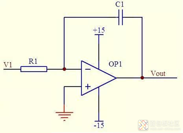
Op-amp integrator circuit
Vout = −(1/(R₁C₁)) ∫V₁ dt
For constant DC input Vi: Vout = −Vi·t/(R₁C₁)
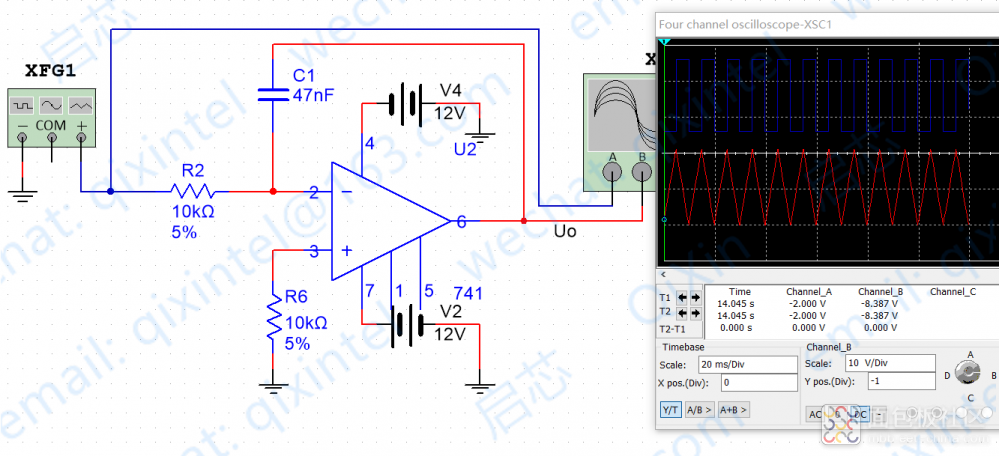
Integrator simulation (input square wave, output sawtooth wave)
Differentiator
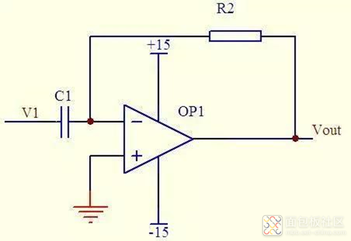
Op-amp differentiator circuit
Vout = −R₂C₁ · dV₁/dt
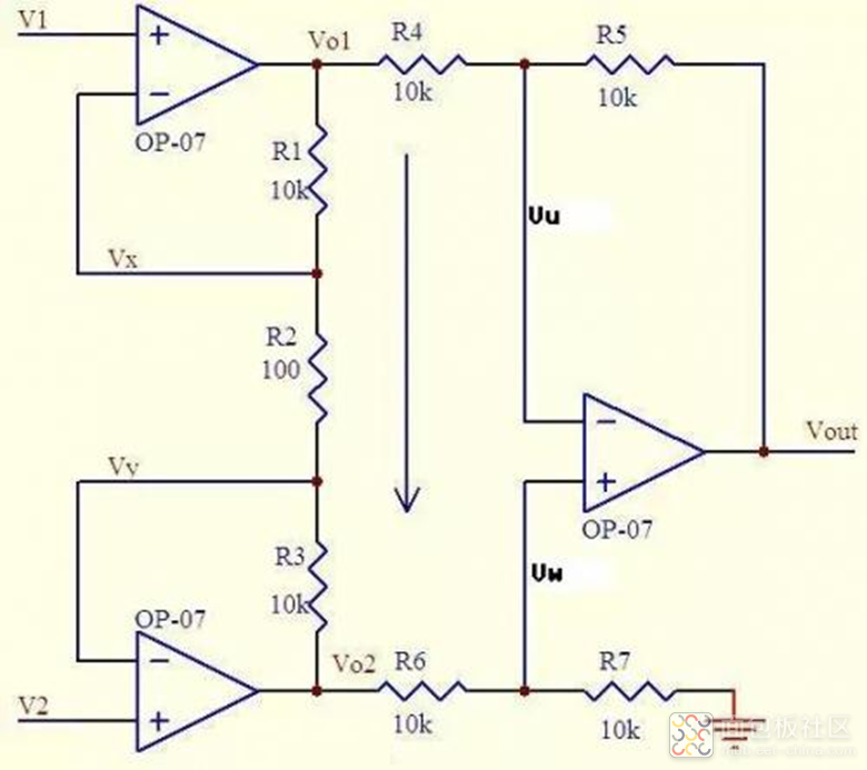
Differential Amplifier (High CMRR)
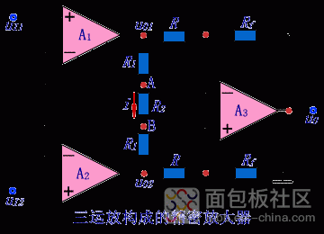
High-CMRR differential amplifier
Gain A = 1 + 2R₁/R₂
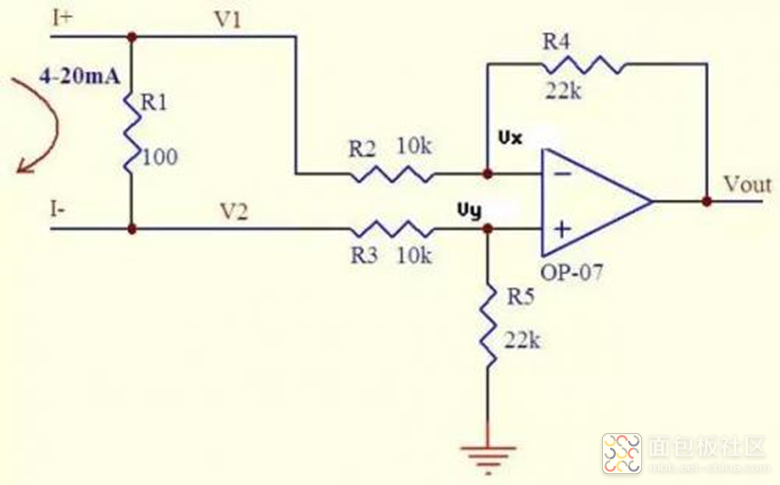
Current-to-Voltage Converter (4–20 mA)
4–20 mA current to voltage circuit
Converts 4–20 mA to −0.88 ~ −4.4 V for ADC input.
Voltage-to-Current Converter
Voltage-to-current converter circuit
Output current through R₇ is I = Vi/R₇, suitable for driving loads.
With these methods, you can analyze nearly all op-amp circuits step by step.
About Maxipcb
Maxipcb empowers innovators to turn cutting-edge technologies into reality.
We offer one-stop solutions for design, simulation, testing, PCB manufacturing, component procurement and SMT assembly, enabling efficient development, rapid deployment and risk control across the full product lifecycle.Serving the world in communications, industrial automation, aerospace, automotive, semiconductor and beyond, we build a safer, more connected future together.

 Inverting op-amp circuit diagram
 Non-inverting op-amp circuit diagram
 Inverting adder circuit diagram
 Simulation with R₁=R₂=R₄ → VO = V₁+V₂
 Simulation with R₂=R₄, R₁=3R₂ → VO=3(V₁+V₂)
 OP07C low-frequency noise amplifier circuit
 Non-inverting adder circuit diagram
 Differential subtractor circuit
Analysis gives: Vout = V₂ − V₁
Differential subtractor circuit
Analysis gives: Vout = V₂ − V₁ Op-amp integrator circuit
Vout = −(1/(R₁C₁)) ∫V₁ dt
For constant DC input Vi: Vout = −Vi·t/(R₁C₁)
Op-amp integrator circuit
Vout = −(1/(R₁C₁)) ∫V₁ dt
For constant DC input Vi: Vout = −Vi·t/(R₁C₁) Integrator simulation (input square wave, output sawtooth wave)
 Op-amp differentiator circuit
Vout = −R₂C₁ · dV₁/dt
Op-amp differentiator circuit
Vout = −R₂C₁ · dV₁/dt


