The commonly used PCB substrates are all FR-4 materials, and the adhesion strength and working temperature of copper foil are relatively high. Generally, the allowable temperature of PCB is 260℃, but the highest temperature of PCB actually used should not exceed 150℃, because if it exceeds this temperature, it will be close to the melting point of solder (183℃). At the same time, the allowable temperature of components on the board should also be taken into account.
The commonly used PCB substrates are all FR-4 materials, and the adhesion strength and working temperature of copper foil are relatively high. Generally, the allowable temperature of PCB is 260℃, but the highest temperature of PCB actually used should not exceed 150℃, because if it exceeds this temperature, it will be close to the melting point of solder (183℃). At the same time, the allowable temperature of components on the board should also be taken into account. Generally, civilian-grade IC can only withstand up to 70℃, industrial-grade IC is 85℃, and military-grade IC can only withstand up to 125℃. Therefore, the temperature of copper foil near IC on PCB with civilian IC should be controlled at a low level, and higher PCB temperature can be allowed only on the board with high temperature-resistant high-power devices (125℃ ~ 175℃), but the influence of higher PCB temperature on heat dissipation of power devices should also be considered.
Generally, PCB is usually made of copper foil with a thickness of half an ounce (about 18μm) without special instructions. 1oz (about 35μm) copper foil thickness is more expensive, 2oz (about 70μm) copper foil thickness is more expensive, and it is rarely used. Copper foil thickness of 3oz (about 105μm) and above usually needs to be customized if there are special needs.
Relationship between width and current of copper foil with thickness of 1oz/1.5oz/2oz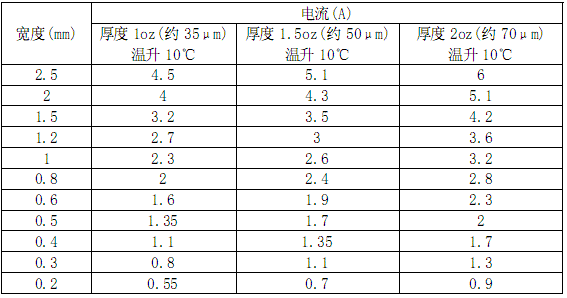
Note: The current carrying capacity of copper foil width when using copper skin as conductor to pass through heavy current should be selected and considered with reference to the numerical derating of 50% in the table, and then look at the empirical formula extracted from < < Practical Anti-interference Technology of Electronic Circuits > > (National Defense Industry Press, Mao Nan Sun Ying 96.1 first edition). The following original text is extracted:
"Due to the limited thickness of copper-clad copper foil, the current-carrying capacity of copper foil should be considered in the strip-shaped copper foil that needs to flow a large current. Taking the typical 0.03mm thickness as an example, if the copper foil is used as a strip-shaped conductor with a width of W(mm) and a length of L(mm), its resistance is 0.0005*L/W Ohm. In addition, the current-carrying capacity of copper foil is also related to the types, quantities and
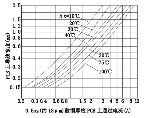
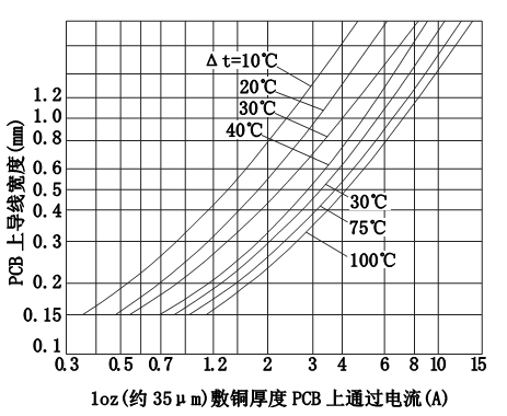
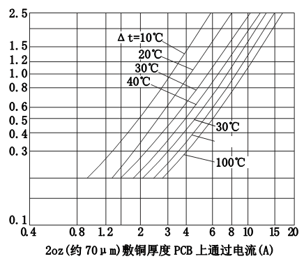
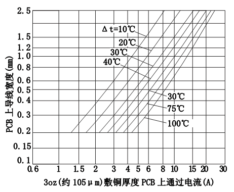
Relationship between copper foil with different width and thickness and current
 About MaxipcbMaxipcb inspires and empowers innovators and helps them bring world-changing technologies to life. We provide advanced design, simulation and testing solutions to help engineers complete development and deployment faster in the whole product life cycle, while controlling risks. Our customers are all over the world, such as communication, industrial automation, aerospace and national defense, automobile, semiconductor and general electronics. We join hands with customers to accelerate innovation and create a safe and interconnected world.
