Common types of circuit board short circuits are classified as follows by function: soldering shorts (e.g., solder bridging), PCB internal shorts (e.g., residual copper, misaligned vias), component shorts, assembly shorts, ESD/EOS breakdown, inner-layer micro-shorts in circuit boards, electrochemical shorts (e.g., chemical residues, electromigration), and shorts caused by other reasons.
Common types of circuit board short circuits are classified as follows by function: soldering shorts (e.g., solder bridging), PCB internal shorts (e.g., residual copper, misaligned vias), component shorts, assembly shorts, ESD/EOS breakdown, inner-layer micro-shorts in circuit boards, electrochemical shorts (e.g., chemical residues, electromigration), and shorts caused by other reasons. By routing characteristics, shorts are divided into: line-to-line shorts, line-to-plane (layer) shorts, and plane-to-plane (layer-to-layer) shorts.
6 Methods for Troubleshooting PCB Short Circuits
-
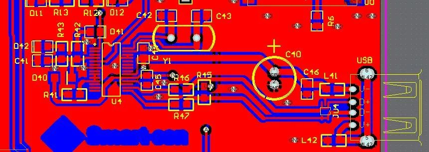
Open the PCB design file on a computer, highlight the shorted net, and check the locations with the closest spacing that are most prone to bridging, especially paying attention to shorts inside integrated circuits (ICs).
-
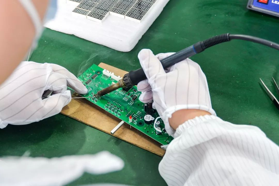
For manual soldering, develop good habits:
- Visually inspect the PCB before soldering, and use a multimeter to check whether key circuits (especially power and ground) are shorted;
- After soldering each chip, use a multimeter to verify whether the power and ground are shorted;
- Do not flick the soldering iron randomly during soldering. If solder splashes onto chip pads (especially surface-mount devices), the short will be difficult to locate.
-
Once a short is detected, isolate circuit blocks by cutting traces (especially suitable for single/double-layer boards), power each functional block separately, and troubleshoot step by step.
-
Use short-circuit location analyzers. For specific scenarios, professional testing equipment delivers higher efficiency and accuracy.
-
For designs with BGA chips—where all solder joints are covered by the chip and invisible, and the board is a multi-layer board (4 layers or more)—it is best to split the power supply for each chip during design, connecting them with magnetic beads or 0Ω resistors. When a power-to-ground short occurs, disconnect the magnetic beads for testing to easily locate the faulty chip. BGA soldering is highly difficult; manual soldering can easily short adjacent power and ground solder balls if not performed carefully.
-
Be extremely careful when soldering small-sized surface-mount capacitors, especially power supply filter capacitors (103 or 104). Large quantities of these capacitors easily cause power-to-ground shorts. In some cases, the capacitor itself may be shorted, so it is best to test capacitors before soldering.
In circuit board repair, troubleshooting a common power supply short is often challenging because multiple components share the same power rail, and every component connected to this rail is a potential short source. If the board has few components, the "blanket troubleshooting" method can eventually locate the short; if there are many components, success depends on luck.
For through-hole capacitors on the board, use diagonal cutters to snip one lead (snip at the middle, not flush with the component or the board). For through-hole ICs, snip the VCC power pin. If the short disappears after cutting a pin, the corresponding chip or capacitor is faulty. For surface-mount ICs, melt the solder on the power pin with a soldering iron and lift the pin to disconnect it from the VCC rail. After replacing the faulty component, re-solder the cut or lifted connection.
A faster method requires a specialized instrument: a milliohm meter. Copper foil on a PCB has resistance. For a PCB with 35μm-thick copper foil and 1mm-wide traces, the resistance is approximately 5mΩ per 10mm length—too small to measure with a standard multimeter, but detectable with a milliohm meter.
Assume a component is shorted: a standard multimeter reads 0Ω, while a milliohm meter shows tens to hundreds of milliohms. The lowest resistance reading will appear when the probes are placed directly on the shorted component (readings on other components include trace resistance). By comparing resistance values with a milliohm meter, the component with the minimum resistance is the prime suspect (the same logic applies to solder or copper foil shorts).
How to Quickly Locate VCC-to-GND Shorts?
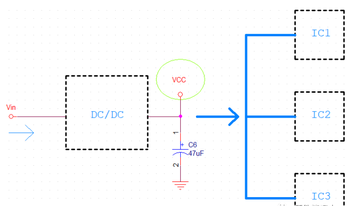
Hardware engineers frequently encounter VCC-to-GND short circuits. For clarity, a simplified schematic is provided. Motherboards typically take a DC input voltage Vin, convert it to the desired voltage via a DC/DC chip, and supply power to MCUs, op-amps, CPUs, and other chips. As shown in the diagram, VCC powers IC1, IC2, and IC3 simultaneously. How to troubleshoot if VCC is shorted to ground?
First, confirm it is a genuine short. Some power supply filter capacitors have large capacitance; if measured immediately after power-off, VCC and GND may show continuity because the capacitor is not fully discharged—this is not a real short. After confirming a VCC-to-GND short, use the following methods:
1. Elimination Method
Isolate nets connected to VCC one by one to find the root cause. First, disconnect Node 1 in the diagram. If the short is resolved, the fault is in the rear-stage circuit; then disconnect Nodes 2, 3, and 4 sequentially. If the short persists, the DC/DC chip itself is faulty and can be removed.
In some cases, the short remains even after these steps. I once encountered this issue caused by a breakdown of 0.1μF ceramic capacitors—further inspection revealed incorrect capacitor selection with insufficient voltage rating, leading to mass board rework. Therefore, filter capacitors connected to VCC must also be inspected, though they rarely fail under normal conditions.
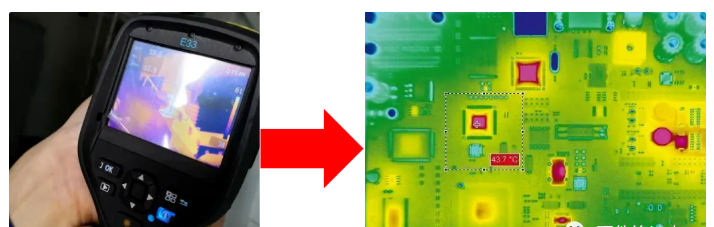
2. Thermal Imager Method
This is a simple method: apply a low voltage slowly and observe with a thermal imager. The component that heats up the fastest (and becomes excessively hot) is the faulty one and can be replaced. Most companies are equipped with thermal imagers; request one if unavailable.
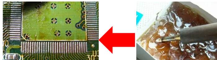
3. Rosin Method
Apply a layer of rosin flux around chips connected to the 5V net (e.g., IC1, IC2, IC3, and the DC/DC chip). The chip whose rosin melts first is the shorted component. A short causes large current and high power dissipation, generating significant heat (chip temperature can exceed 100℃ during testing), which melts the rosin.
Finally, for newly fabricated prototype boards, perform a visual inspection first—solder debris shorts or missing through-hole components can be spotted at a glance. Ensuring a normal first power-on saves substantial repair time.
About Maxipcb
Maxipcb empowers innovators to turn cutting-edge technologies into reality.
We offer one-stop solutions for design, simulation, testing, PCB manufacturing, component procurement and SMT assembly, enabling efficient development, rapid deployment and risk control across the full product lifecycle.Serving the world in communications, industrial automation, aerospace, automotive, semiconductor and beyond, we build a safer, more connected future together.


